0. Introduction
In the previous chapter, we introduced the basic usage of linking ROS with MATLAB. In this chapter, we will learn how to use Simulink in MATLAB.
Simulink’s support for the Robot Operating System (ROS) allows us to create Simulink models that work with the ROS network. ROS is a communication layer that enables different components of a robotic system to exchange information in the form of messages.
Components send messages by publishing them to specific topics (e.g., /odometry). Other components receive messages by subscribing to that topic. The content of this article is based on modifications of a post by Mu Yu.
Since the use of Simulink has not changed much between ROS1 and ROS2, we will only introduce ROS1.
The Simulink support for ROS includes a Simulink block library for sending and receiving messages for specified topics. When you simulate the model, Simulink connects to the ROS network, which can run on the same machine as Simulink or on a remote system. Once this connection is established, Simulink will exchange messages with the ROS network until the simulation ends.
If you have Simulink Coder installed, you can also generate standalone ROS components or nodes in C++ code from Simulink models.
Additionally, the Simulink support for ROS1 and ROS2 is not the same. The ROS toolbox does not support the following ROS features in Simulink: ROS Service server, ROS actions, and TF trees.
If your application requires these features, you will need to use MATLAB’s ROS functionalities. You can write ROS nodes in MATLAB that can publish service servers, actions, and TF trees as ROS messages to topics.
Then, Simulink can subscribe to those topics to process these messages. Use the following functions in MATLAB to handle these features:
-
ROS service server:rosservice, rosvcserver
-
ROS actions:rosaction, rosactionclient
-
Transform tree:rostf, transform, getTransform
For ROS 2, Simulink only supports publishing and subscribing functionalities.
To see the complete list of ROS support in Simulink, please refer to https://ww2.mathworks.cn/help/ros/ros-in-simulink.html
1. Initialize ROS and Establish Connection
1. Enter the following command in the terminal to check the local address:
ifconfig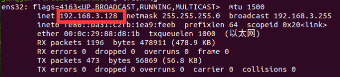
2. Write the local IP into the .bashrc file. Open the home folder, press Ctrl+h to show hidden files, select .bashrc and open it. Add the following command at the end (replace the IP with your computer’s IP), and then save and exit.
export ROS_IP=192.168.3.128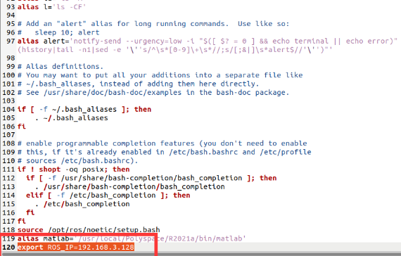
3. Start roscore and obtain the IP output by ROS. Enter roscore in the terminal to start it, and you will see that roscore outputs an IP as shown in the figure below:
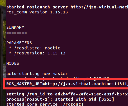
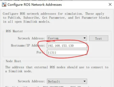
4. Open MATLAB and establish a connection with ROS. In the command window of MATLAB, enter the following statement; the latter part is the ROS output IP we obtained in the previous step.
setenv('ROS_MASTER_URI','http://jzx-virtual-machine:11311') rosinit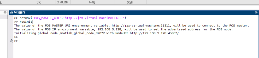
2. Create a Publisher
Configure a block and send a geometry_msgs/Point type message to the /location node.
Follow these steps:
1. In the MATLAB toolbar, select Home>Simulink to open the Simulink start page.
2. On the Simulink start page, click on the blank model to create and open a new Simulink model.
3. In the Simulink toolbar, select Simulation > Library Browser to open the Simulink library browser. Click on the ROS toolbox tab (you can also type roslib in the MATLAB command window). Select the ROS library.
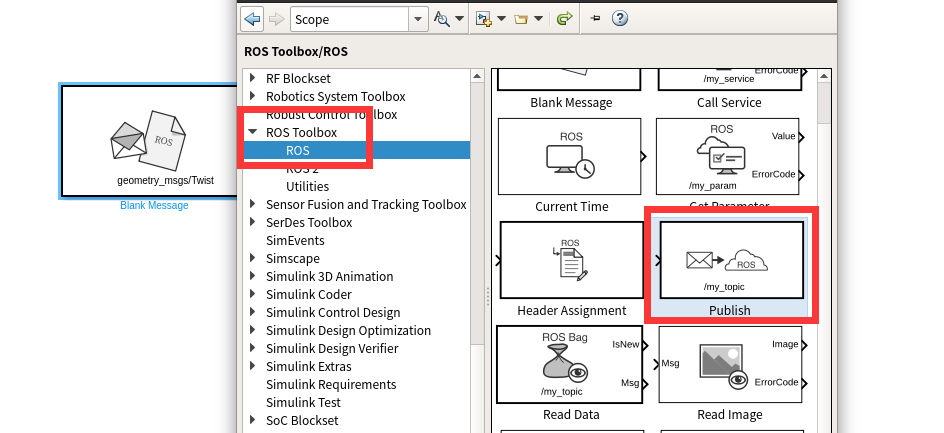
4. Drag the Publish block into the model. Double-click the block to configure the topic and message type.
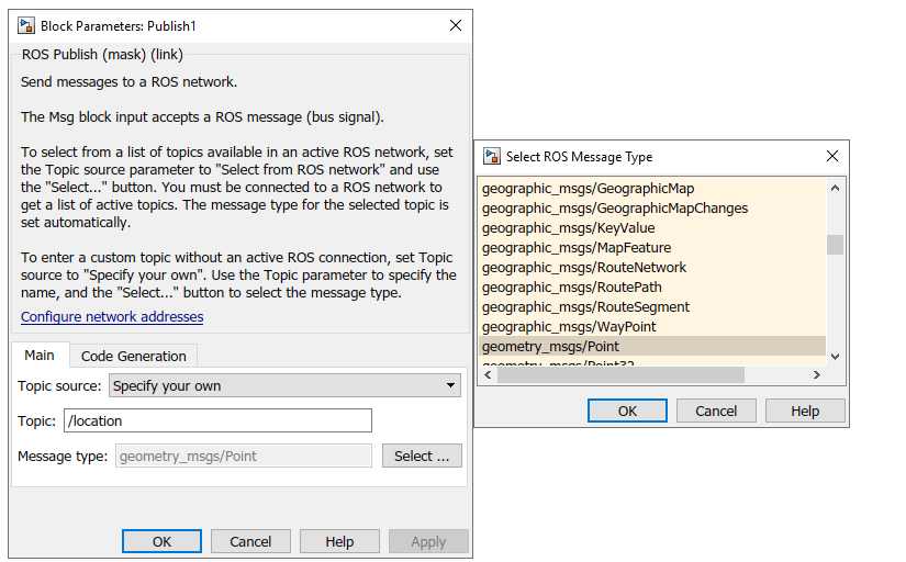
5. For the Topic source, select Specify your own and enter /location in the Topic field.
6. Click the Select button next to Message type. A pop-up window will appear. Choose geometry_msgs/Point and click OK to close the pop-up window.
3. Create a Message
Create a blank ROS message and fill it with the X and Y positions of the robot path. Then publish the updated ROS message to the ROS network.
A brief introduction to the Blank Message module: The Blank Message module creates a blank message of the specified message or service type. The output of the Msg block is a blank ROS message (bus signal).
Set the Class parameter to select ROS messages, service requests, and service response messages. Here we are using ROS messages (bus signal). You can use the bus assignment block to modify specific fields in the bus signal. The bus signal is initialized to zero (ground).
Specific operations are as follows:
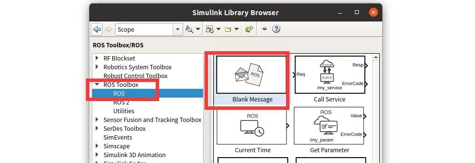
1. In the library browser, click on the ROS toolbox tab, or type roslib in the MATLAB command line to select the ROS library.
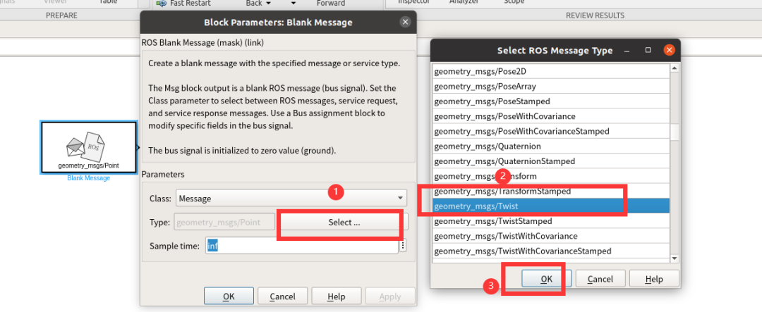
2. Drag the Blank Message block into the model. Double-click the block to open the block information.
3. Click the Select button next to the Message type box and choose geometry_msgs/Twist from the pop-up window.
4. We also need a Publish module to publish the information, double-click to open it and set it as shown in the figure below, since we want to publish to /turtle1/cmd_vel to control the turtle’s movement, we select the /turtle1/cmd_vel topic here.
5. As mentioned above, the output of the Blank Message is a blank ROS message (bus signal), we can use the Bus Assignment block to modify specific fields in the bus signal. So we also need a Bus Assignment module, which can be dragged out from the Simulink > Signal Routing library.
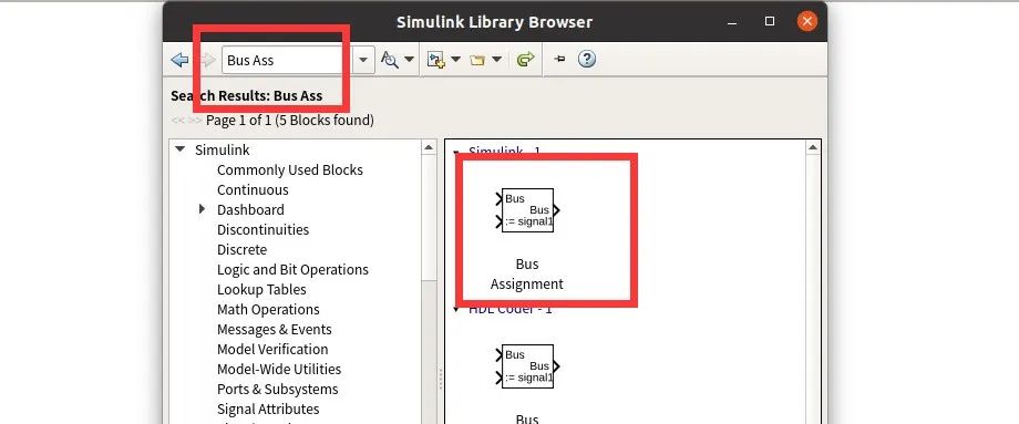
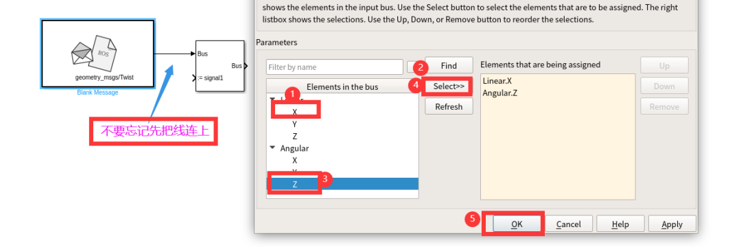
6. Connect the output port of the Blank Message block to the bus input port of the Bus Assignment block. Then connect the output port of the Bus Assignment block to the input port of the ROS Publish block. Double-click the Bus Assignment block. You should see message information; the Bus Assignment block allows the elements in the bus to be assigned new values.
The left list box displays the elements in the input bus. Use the select button to choose the elements to assign. Use the up, down, or remove buttons to rearrange the selections. Here we select the X-axis linear velocity and Z-axis angular velocity as shown in the figure below:
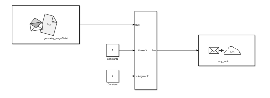
7. Connect as shown in the figure below; here we set the linear velocity to a constant of 10 and the angular velocity to a constant of 7.
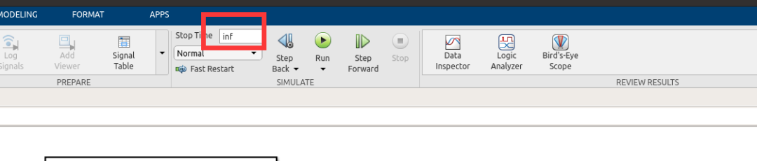
8. Also, change the simulation time to inf.
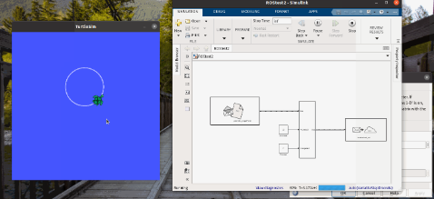
9. Click Run to start the simulation. Simulink creates a dedicated ROS node for the model and creates a ROS publisher corresponding to the Publish block. While the simulation is running, enter rosnode list in the MATLAB command window.
This lists all available nodes in the ROS network, including a node named /untitled_81473 (the model name plus a random number to make it unique). While the simulation is running, enter rostopic list in the MATLAB command window. This lists all available topics in the ROS network, including /location.
4. Create a Subscriber
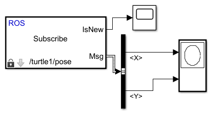
10. From the ROS Toolbox tab in the Library Browser, drag the Subscribe block into the model. Double-click the block.
11. In the Topic source box, select Specify your own, and enter “/turtle1/pose” in the Topic box.
12. Click the Select button next to the Message type box and choose Turtlesim/Pose from the pop-up window.
13. The Subscribe block outputs a Simulink bus signal, so you need to extract the X and Y signals from it. However, the Subscribe module is effectively an empty module.
14. Still in Simulink > Signal Routing, select a Bus Selector to receive the signals.
15. Add a Bus Selector and add X and Y to the right side, then connect it to the output of the subscribe block. For the other port of the subscribed topic, we can place a Scope block to record it.
16. Drag and drop an “XY Graph” block into the model. Connect the output port of the “Bus Selector” to the input port of the “XY Graph”.
17. After configuring the above, set the Simulink simulation time to inf, click run, and control the turtle movement on Ubuntu. You can see that the turtle’s pose on Ubuntu is consistent with that in Simulink.
5. New Message Trigger Response
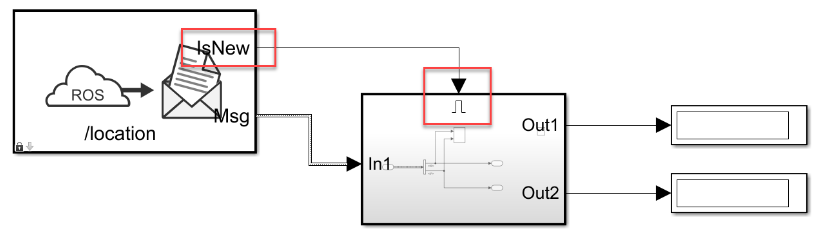
For subscribers, often we only need them to trigger a response to new messages; if no messages are received, they will output a blank message.
1. In the model, click and drag to select the Bus Selector block and the XY Graph block. Right-click the selected area and select Create Subsystem from the selection.
2. From the Simulink library, drag an Enable module from Simulink > Ports & Subsystems into the newly created subsystem.
3. Connect the IsNew output of the Subscribe block to the enable input of the subsystem, as shown in the figure below, and remove the Terminator module. This way, the IsNew output will only be true if a new message was received in the previous time step.
6. Simulink Automatically Generates ROS Code
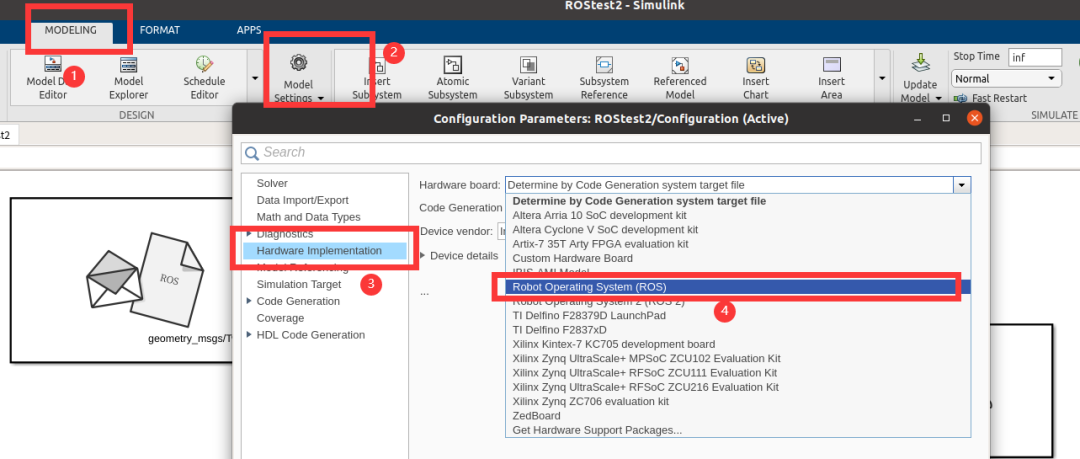
Once we have completed the control program using Simulink, we hope to directly control ROS next time without needing to start MATLAB and Simulink every time. Therefore, we can use Simulink’s code generator to generate ROS code. Before generating the code, we need to make the following settings.
Open the settings as shown in the figure, select Hardware implementation, then choose Robot Operating System, and click OK.
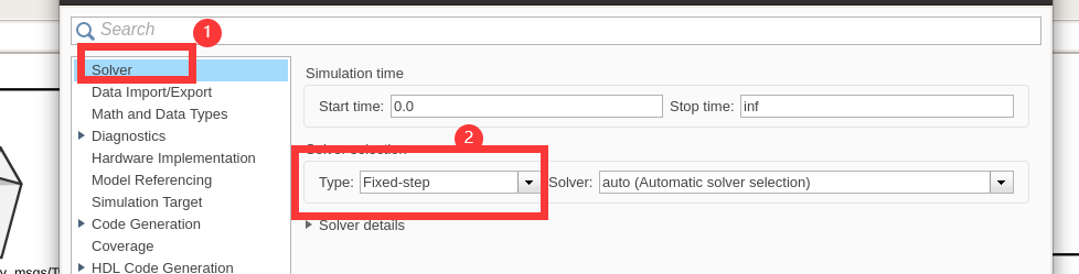
Check the Type in the Solver to ensure it is set to Fixed-step, and note that the solver must be discrete.
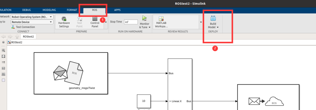
Open Build Model as shown in the figure.
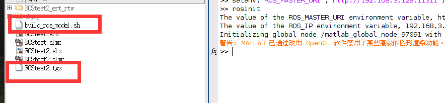
After completion, a sh file and a tgz file will be generated.
Find the folder where the above files are located, right-click to open in the terminal, and enter the following command.
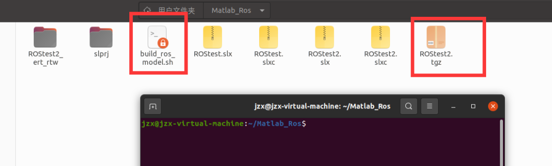
Then compile the code to complete the same functionality as Simulink.
cd ~/catkin_ws/catkin_makecatkin_make install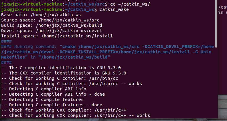
7. Custom Message
When our message is more complex, we usually need to use custom messages. MATLAB versions 2020b and above come with the ROS Toolbox Interface for ROS Custom Messages tool. If you are below this version, you need to download it via the link for the ROS Toolbox Interface for ROS Custom Messages.
The directory structure for compiling custom messages must be specific, i.e., there should be a folder containing the ROS package, which can hold multiple ROS packages, and then place its ROS message under the msg/ directory of that package, and service files under the srv/ directory of that package. Here is the basic ROS directory; let’s take a look at the directory structure:
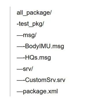
Then use the rosgenmsg command in MATLAB to compile the msg information. This is our path.
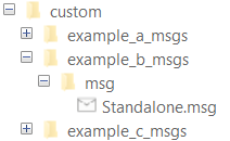
% Note that this directory is to the large directory, not in the package directory% folderpath = "./all_package"folderPath = fullfile(pwd,"custom");copyfile("example_*_msgs",folderPath);rosgenmsg(folderpath)% ros2genmsg(folderPath) %ros2After compilation, a custom folder will be generated in the large directory.
Identifying message files in folder ‘C:/Work/custom’.Done.Removing previous version of Python virtual environment.Done.Creating a Python virtual environment.Done.Adding required Python packages to virtual environment.Done.Copying include folders.Done.Copying libraries.Done.Validating message files in folder ‘C:/Work/custom’.Done.[3/3] Generating MATLAB interfaces for custom message packages… Done.Running colcon build in folder ‘C:/Work/custom/matlab_msg_gen/win64’.Build in progress. This may take several minutes…Build succeeded.build logros2 msg list-
example_a_msgs/DependsOnB
-
example_b_msgs/Standalone
-
example_c_msgs/DependsOnB
MATLAB prompts that after performing the following three operations, you can use addpath to add the message location to the MATLAB path and use savepath to save these changes.
1. Edit javaclasspath.txt, add the following file location as a new line, and save the file:
D:\matlabDemo\ros-messages\custom\jar\test_pkg-0.0.0.jar2. Add the custom message folder to the MATLAB path by executing the following command:
addpath('D:\matlabDemo\ros-messages\custom\msggen') savepath3. Restart MATLAB and verify that you can use the custom message. Enter “rosmsg list” and ensure that the output includes the generated custom message types.
Note: The javaclasspath.txt file is placed in the prefdir directory, which can be viewed by entering the prefdir command in the MATLAB command line.
Particularly important: In practice, placing the javaclasspath.txt in the prefdir directory, by checking related issues, can allow it to be launched from a shortcut; if the javaclasspath.txt is placed in the bin/ directory, which is the MATLAB startup directory, after restarting MATLAB, you can check the msg, but cannot start from the shortcut, you must start from matlab.exe in the bin directory. Therefore, it is best to place this file in the prefdir directory.
# Place javaclasspath.txt in the prefdir directory, and you can find the message through rosmsg list# However, when viewing specific message content, it will report an errorrosmsg show test_pkg/BodyIMUHow to Implement Robotic Arm Grasping Based on Visual Depth Reinforcement Learning
This course mainly explains the following aspects in detail: 1. How to encapsulate your own environment in PyBullet; 2. The ins and outs of the PPO algorithm and its code implementation; 3. How to handle reinforcement learning problems with visual input;

(Scan the QR code to view course details)