
NB-IoT and eMTC both belong to the cellular IoT and share the “3C” characteristics of cellular IoT:
• Coverage Enhanced Coverage
• Consumption Low Power Consumption
• Cost Low Cost
To meet the “3C” goals, NB-IoT and eMTC have different implementation methods, as detailed below:
1
Key Technology Comparison of NB-IoT and eMTC
Enhanced Coverage
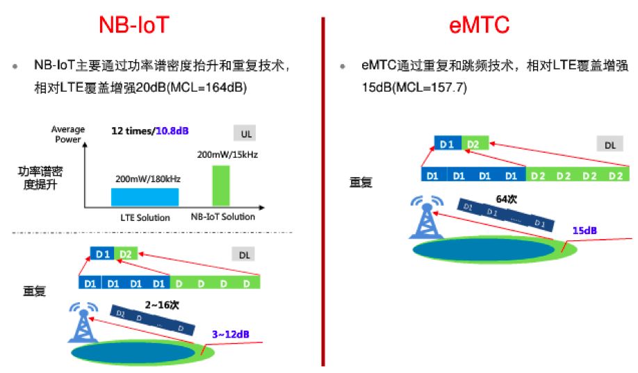
NB-IoT’s coverage target is MCL 164dB, and its coverage enhancement is mainly achieved by increasing the uplink power spectral density and retransmissions.
eMTC’s coverage target is MCL 155.7dB, with a power spectral density equal to LTE, and coverage enhancement is mainly achieved through retransmissions and frequency hopping.
MCL (Maximum Coupling Loss) refers to the path loss from the base station antenna port to the terminal antenna port. From the coverage targets, eMTC is about 8dB lower than NB-IoT.
How Does Retransmission Enhance Coverage?
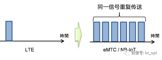
Retransmission means sending a transmission block over multiple subframes. Repetition Gain=10log Repetition Times, meaning that retransmitting twice can increase the signal by 3dB. NB-IoT supports a maximum of 2048 downlink retransmissions and 128 uplink retransmissions.
Both NB-IoT and eMTC use retransmissions to enhance coverage.
How Does Increasing Uplink Power Spectral Density Enhance Coverage?
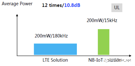
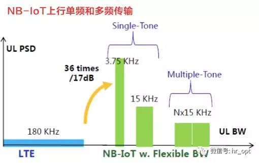
Uplink control information and service information are sent in a narrower LTE bandwidth, resulting in greater PSD (Power Spectrum Density) gain under the same transmission power, reducing the demodulation requirements for the receiver.
In the downlink direction, if NB-IoT uses a standalone deployment mode, the downlink transmission power can be independently configured, with a power spectral density equal to GSM but about 14dB higher than LTE FDD.
In the uplink direction, due to NB-IoT’s minimum scheduling bandwidth of 3.75K or 15K, the uplink power spectral density can be enhanced by up to 17dB. Considering that GSM terminal transmission power can reach up to 33dBm, while NB-IoT’s maximum transmission power is 23dBm, the actual power spectral density of NB-IoT terminals can be about 7dB higher than GSM terminals.
eMTC shares transmission power and system bandwidth with LTE, with no enhancement in power spectral density, mainly achieving coverage enhancement through retransmissions and frequency hopping.
For NB-IoT, it is worth mentioning:
•In the downlink direction, only the power in standalone deployment can be independently configured, while the power in in-band and guard band deployment modes is limited by LTE power. Therefore, in in-band and guard band deployment modes, NB-IoT requires more retransmissions to achieve coverage levels comparable to those in standalone deployment mode.
•In the uplink direction, there is basically no difference among the three modes.
Low Power Consumption
In terms of low power consumption, NB-IoT and eMTC use the same technologies, including: PSM, eDRX, and extended cycle timers.
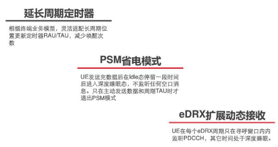
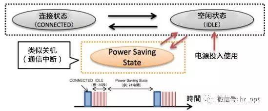
① PSM (Power Saving Mode)
Mobile phones need to be on standby at all times; otherwise, what if someone calls you and can’t reach you? However, this means the phone must occasionally listen to the network, which consumes power.
However, IoT terminals are different from mobile phones; they spend most of their time in deep sleep. They may only report one or two messages a day or even a week, and after staying in idle state for a period, they enter deep sleep without needing to listen for messages.
PSM allows IoT terminals to enter deep sleep mode after sending data, similar to turning off, without any communication activity.
② eDRX
DRX (Discontinuous Reception) refers to the non-continuous reception. eDRX is an extended version of discontinuous reception.
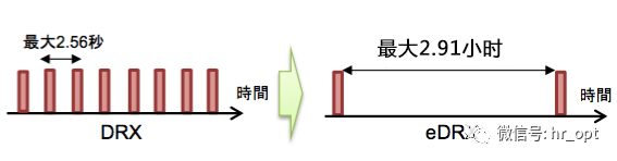
Mobile phones can intermittently receive signals to save power. NB-IoT and eMTC have extended this intermittent interval for greater power savings.
③ Extended Cycle Timer
Flexibly configure long cycle location update timers (RAU/TAU) to reduce wake-up frequency.
Low Cost
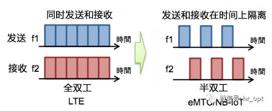
Ways to reduce costs include minimizing protocol stack processing overhead, using single antennas and FDD half-duplex mode to lower RF costs, and low data rates and bandwidth inherently mean reduced complexity for chip processing, etc.
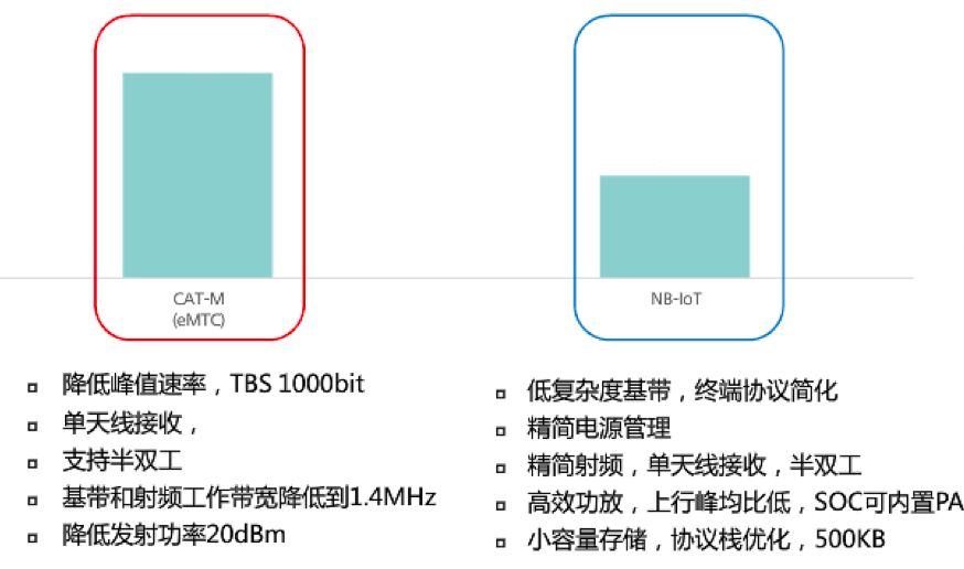
For example, FDD half-duplex mode means that sending and receiving do not need to be processed simultaneously, making it cheaper and more power-efficient compared to full duplex.
2
Technical Parameter Comparison of NB-IoT and eMTC
The main differences between NB-IoT and eMTC are:
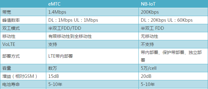
NB-IoT aims for the lowest cost, longest battery life, no mobility, and very low data rates. It is more suitable for applications with no mobility, small data volumes, insensitivity to latency, and high sensitivity to cost, such as smart parking, smart lamp posts, and smart metering.
To meet more application scenarios and market demands, Re-14 and subsequent versions will enhance NB-IoT with a series of technologies, including adding positioning and multicast capabilities, providing higher data rates, paging and random access on non-anchor carriers, enhancing mobility in connected states, and supporting lower UE power levels.
eMTC supports voice, has faster transmission rates, and supports mobility, but the module cost is relatively high, making it suitable for wearable devices, health monitoring, indoor mobile applications, etc.
3
Comparison of Deployment Methods for NB-IoT and eMTC
NB-IoT Deployment Methods
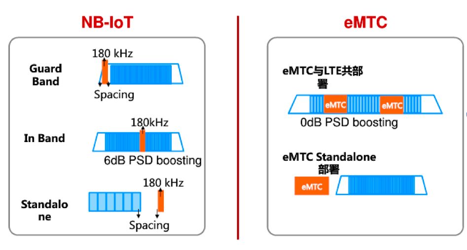
NB-IoT has three deployment methods: standalone deployment, guard band deployment, and in-band deployment.
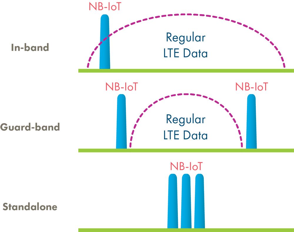
Standalone deployment is suitable for reusing the GSM frequency band, where the GSM channel bandwidth is 200KHz, leaving space for NB-IoT’s 180KHz bandwidth, with 10KHz protection intervals on both sides.
Guard band deployment utilizes unused resources in the LTE edge protection bandwidth, while in-band deployment utilizes any resource block in the LTE carrier. However, in in-band deployment mode, some PRBs cannot be occupied by NB-IoT.
eMTC Deployment Methods
eMTC supports co-deployment with LTE and independent deployment.
It mainly uses the in-band deployment method, supporting both TDD and FDD modes. eMTC and LTE work together in the same frequency band, with unified resource allocation by the base station, sharing some control channels. Therefore, operators can directly deploy eMTC within existing LTE frequency bands without needing to allocate separate spectrum.
4
Physical Layer Technology Comparison of NB-IoT and eMTC
4.1 Comparison of Time-Frequency Domain Structures
NB-IoT
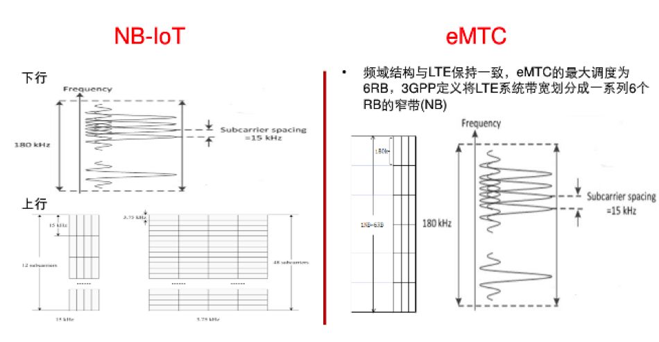
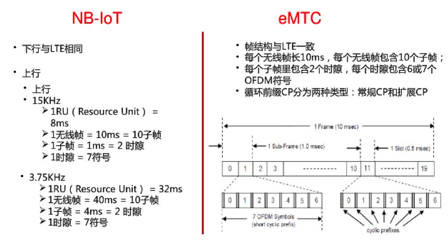
Downlink:
NB-IoT downlink is consistent with LTE, using Orthogonal Frequency Division Multiple Access (OFDMA) technology, with a subcarrier spacing of 15kHz, and time slots, subframes, and radio frames of 0.5ms, 1ms, and 10ms respectively, including the number of OFDM symbols per time slot and cyclic prefix (cyclic prefix) being the same as LTE.
NB-IoT carrier bandwidth is 180KHz, equivalent to the bandwidth of one PRB (Physical Resource Block) in LTE, i.e., 12 subcarriers * 15KHz/subcarrier = 180KHz, ensuring downlink compatibility with LTE. For example, when using LTE carrier in in-band deployment, the downlink NB-IoT PRB maintains orthogonality with other LTE PRBs.
Uplink:
NB-IoT uplink supports multi-tone and single-tone transmissions.
Multi-tone transmission is based on SC-FDMA, with a subcarrier spacing of 15kHz, 0.5ms time slots, and 1ms subframes (same as LTE).
Single-tone transmission can have subcarrier spacings of 15KHz and 3.75KHz, where 15KHz is the same as LTE to maintain compatibility, while when the subcarrier is 3.75KHz, one time slot in the frame structure is 2ms long (including 7 symbols), and 15KHz is an integer multiple of 3.75KHz, resulting in minimal interference with the LTE system.
eMTC
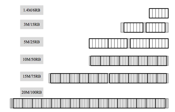
eMTC is an enhanced feature of LTE, with frequency domain structure consistent with LTE, defined in TDD and FDD LTE systems with bandwidths of 1.4M~20MHz. Regardless of the bandwidth in use, eMTC’s maximum scheduling is 6RB, with 3GPP defining LTE system bandwidth as a series of 6RB narrow bands (NB), as shown in the figure below:
eMTC’s frame structure is consistent with LTE.
4.2 Comparison of Physical Channels
NB-IoT Physical Channels
Downlink:
For the downlink, NB-IoT defines three physical channels:
① NPBCH, Narrowband Physical Broadcast Channel
② NPDCCH, Narrowband Physical Downlink Control Channel
③ NPDSCH, Narrowband Physical Downlink Shared Channel
Two physical signals are also defined:
① NRS, Narrowband Reference Signal
② NPSS and NSSS, Primary Synchronization Signal and Secondary Synchronization Signal
Different from LTE, due to NB-IoT’s frequency bandwidth being at most 1 PRB, these downlink physical channels use time-division multiplexing, appearing alternately at different times.
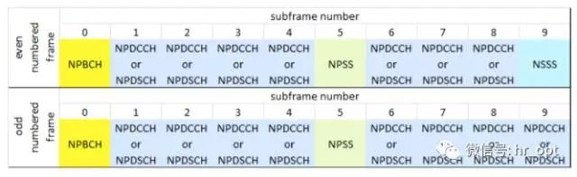
▲Time-division multiplexing of NB-IoT downlink physical channels and signals
As shown in the figure above, NB-IoT subframes are allocated to different physical channels and signals, with each NB-IoT subframe occupying one PRB (12 subcarriers) in the frequency domain and lasting 1ms in the time domain.
NPBCH
NPBCH channel differs from LTE’s PBCH, with a broadcast period of 640ms and repeated 8 times, as shown in the figure below, where the terminal receives several subframe signals for demodulation.
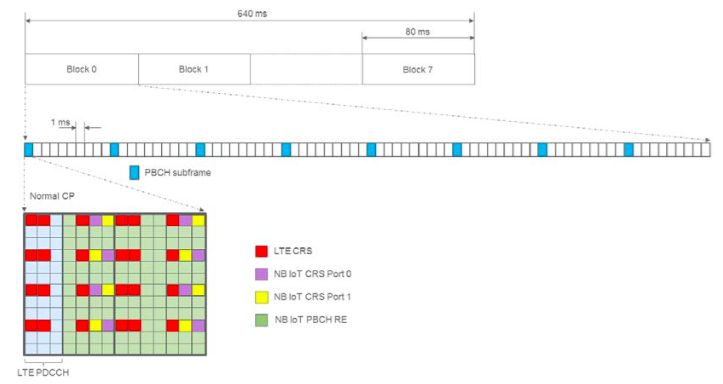
NPBCH is located in subframe #0 of each radio frame, carrying MIB-NB (Narrowband Master Information Block), while other system information such as SIB1-NB is carried on NPDSCH.
NPDCCH
NPDCCH carries scheduling information for uplink and downlink data channels, including HARQ acknowledgment information for uplink data channels, paging indications, and random access response scheduling information, as well as data information from higher layers, paging messages, system messages, and random access response messages.
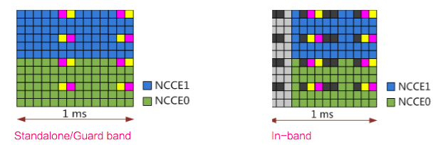
Unlike LTE’s PDCCH, which uses the first few symbols of the subframe, NPDCCH is quite different, using NCCE (Narrowband Control Channel Element) occupying 6 subcarriers in the frequency domain.
In standalone and guard band modes, all OFDM symbols can be used, while in in-band mode, NPDCCH’s control symbols are staggered. NPDCCH has two formats:
• NPDCCH format 0 has an aggregation level of 1, occupying NCCE0 or NCCE1
• NPDCCH format 1 has an aggregation level of 2, occupying both NCCE0 and NCCE1.
NPDCCH’s maximum retransmission count can be configured, with values ranging from {1, 2, 4, 8, 16, 32, 64, 128, 256, 512, 1024, 2048}.
NPDSCH
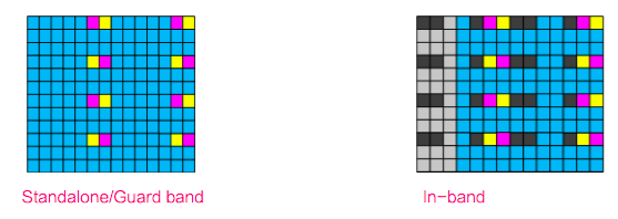
NPDSCH frequency domain resources occupy 12 subcarriers. In standalone and guard band modes, all OFDM symbols are used. In in-band mode, the control domain symbols of LTE must be staggered. Since SIB1-NB indicates the number of control domain symbols, if it is a subframe using NPDSCH, the first three symbols are fixed to be staggered.
NPDSCH modulation is QPSK, with MCS ranging from 0 to 12. Retransmission counts can be {1, 2, 4, 8, 16, 32, 64, 128, 192, 256, 384, 512, 768, 1024, 1536, 2048}.
NRS
NRS (Narrowband Reference Signal), also known as the pilot signal, is primarily used for measuring downlink channel quality estimates, aiding in coherent detection and demodulation at the terminal. NRS is transmitted in all downlink subframes for both broadcast and downlink dedicated channels, regardless of whether data is being transmitted.
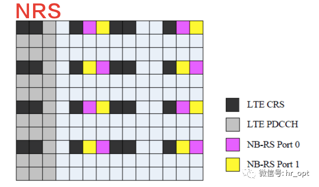
NRS is time-frequency multiplexed with the information-carrying symbols of the subframes carrying NPBCH, NPDCCH, and NPDSCH, using 8 REs per subframe for each antenna port.
NPSS and NSSS
NPSS and NSSS are used for NB-IoT terminals to perform cell search, including time and frequency synchronization and detecting Cell ID. Since LTE’s synchronization sequence occupies 6 PRBs, NB-IoT cannot occupy these 6 PRBs. To avoid conflict, NB-IoT needs to be redesigned.
NPSS is located in subframe #5 of each 10ms radio frame, with a period of 10ms, using the last 11 OFDM symbols of each subframe (as shown below).
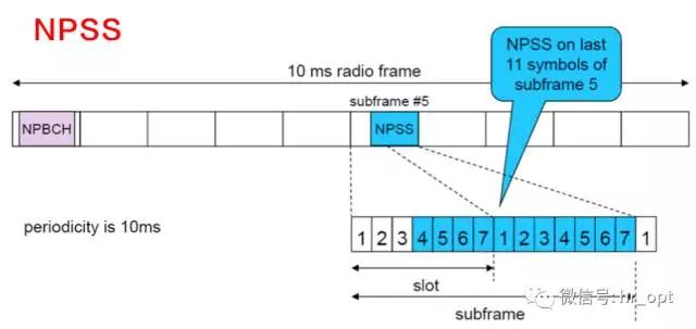
For NB-IoT terminals, executing NPSS detection is a computationally complex process, which contradicts its design goal of simplification. Therefore, NPSS is designed as a short ZC (Zadoff-Chu) sequence.
NSSS is located in subframe #9, with a period of 20ms, appearing only in even frames, and also uses the last 11 OFDM symbols of each subframe.
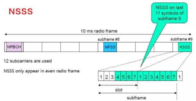
NPSS provides time and frequency synchronization reference signals for NB-IoT terminals. Unlike LTE, NPSS carries no cell information, while NSSS carries PCI.
Uplink:
For the uplink, NB-IoT defines two physical channels:
① NPUSCH, Narrowband Physical Uplink Shared Channel.
② NPRACH, Narrowband Physical Random Access Channel.
Additionally, there is DMRS, the uplink demodulation reference signal.
NPRACH
Since the LTE PRACH channel bandwidth is 1.08MHz, which is far greater than NB-IoT’s uplink bandwidth, it needs to be redesigned.
Unlike LTE’s Random Access Preamble, NB-IoT’s Random Access Preamble uses single-tone transmission with a subcarrier spacing of 3.75kHz, occupying one subcarrier, with Preamble formats 0 and 1 corresponding to CP lengths of 66.7us and 266.7us, respectively, suitable for different cell radii.
Each Random Access Preamble transmission consists of four Symbol Groups, forming one NPRACH channel, where one Symbol Group includes 5 Symbols and 1 CP (as shown below).
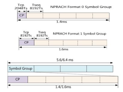
When the CP length is 66.67s (Format 0), the cell coverage radius reaches 10 kilometers. When the CP length is 266.7s (Format 1), the coverage radius reaches 40 kilometers. To extend coverage, the NPRACH channel can achieve coverage enhancement through retransmission, with possible repetition counts of {1, 2, 4, 8, 16, 32, 64, 128}.
NPUSCH
NPUSCH is used to transmit uplink data and uplink control information, with uplink subcarrier spacings of 3.75KHz and 15KHz. There are two transmission modes for uplink: single-carrier transmission (Single tone) and multi-carrier transmission (Multi-tone), where Single tone includes both 3.75KHz and 15KHz subcarrier bandwidths, while Multi-tone has a 15KHz subcarrier spacing, supporting 3, 6, or 12 subcarriers for transmission.
NPUSCH defines two formats: Format 1 and Format 2.
Format 1 is designed for uplink channel data on UL-SCH, using the same Turbo code error correction as LTE, with a resource block size significantly smaller than LTE, not exceeding 1000 bits.
Format 2 is used for HARQ acknowledgment signaling on NPDSCH, transmitting uplink control information (UCI) using repetition codes for error correction.
The minimum unit for mapping to transmission blocks is called a resource unit (RU), determined by NPUSCH format and subcarrier spacing. Uplink transmission resources are allocated in units of RU, with Single tone and Multi-tone RU units defined as follows, with the scheduled RU count being {1, 2, 3, 4, 5, 6, 8, 10}, indicated in NPDCCH N0.
Unlike LTE systems where the basic unit for resource allocation is the subframe, NB-IoT uses the number of subcarriers and time slots as the basic unit for resource allocation:
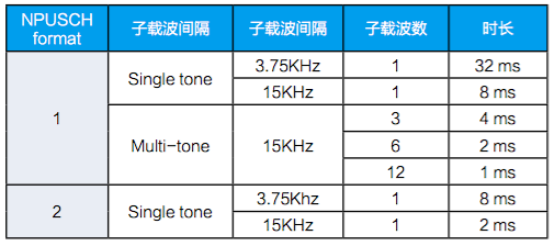
For NPUSCH format 1,
When the subcarrier spacing is 3.75 kHz, only single-tone transmission is supported, with one RU in the frequency domain containing 1 subcarrier and 16 time slots, resulting in a length of 32ms for one RU.
When the subcarrier spacing is 15kHz, both single-tone and multi-tone transmissions are supported, with one RU containing 1 subcarrier and 16 time slots, resulting in a length of 8ms; when one RU contains 12 subcarriers, the time length is equivalent to 2 time slots, i.e., 1ms, which corresponds exactly to a subframe in the LTE system. The time length of resource units is designed as powers of two for more efficient resource utilization, avoiding resource gaps and waste.
For NPUSCH format 2,
RU always consists of 1 subcarrier and 4 time slots, so when the subcarrier spacing is 3.75 kHz, one RU lasts 8ms; when the subcarrier spacing is 15kHz, one RU lasts 2ms.
NPUSCH uses low-order modulation coding schemes MCS 0 to 11, with possible repetition counts of {1, 2, 4, 8, 16, 32, 64, 128}.
DMRS
DMRS is used for channel estimation. NPUSCH Format 1 has the same time slot structure as LTE PUSCH, with 7 OFDM symbols per time slot, with one symbol used as DMRS. Format 2 also has 7 OFDM symbols per time slot, but uses the middle 3 symbols as DMRS.
eMTC Physical Channels
eMTC’s subframe structure is the same as LTE’s. Compared to LTE, eMTC’s downlink PSS/SSS and CRS are consistent with LTE, while PCFICH and PHICH channels are removed, compatible with LTE PBCH, increasing retransmissions to enhance coverage. MPDCCH is designed based on LTE’s EPDCCH, supporting retransmissions, while PDSCH adopts cross-subframe scheduling. Uplink PRACH, PUSCH, and PUCCH are similar to existing LTE structures.
eMTC can define up to four coverage levels, with different PRACH parameters configurable for each coverage level. eMTC is divided into Mode A and Mode B based on different retransmission counts, with Mode A having no or few retransmissions and Mode B having many retransmissions.
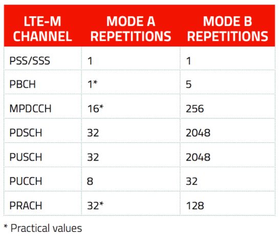
▲Maximum retransmission counts for different channels in eMTC under Mode A and Mode B
Downlink:
PBCH
eMTC PBCH is fully compatible with LTE systems, with a cycle of 40ms, supporting fields indicating eMTC’s cell. It uses retransmissions to enhance coverage, with a maximum transmission of 5 times per transmission.

MPDCCH
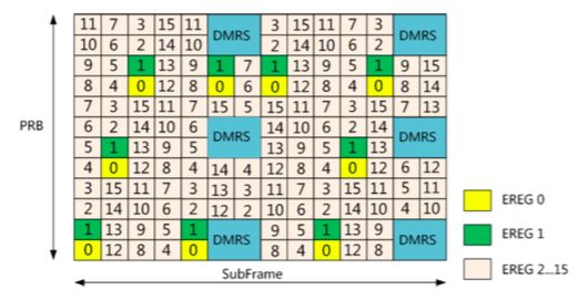
MPDCCH (MTC Physical Downlink Control Channel) is used to send scheduling information, designed based on LTE R11’s EPDCCH, with terminals receiving control information based on DMRS, supporting functions such as control information precoding and beamforming. One EPDCCH transmits one or more ECCE (Enhanced Control Channel Element) resources, with aggregation levels of {1, 2, 4, 8, 16, 32}, with each ECCE consisting of multiple EREG (Enhanced Resource Element Group).
MPDCCH’s maximum retransmission count Rmax can be configured, with values ranging from {1, 2, 4, 8, 16, 32, 64, 128, 256}.
PDSCH
eMTC PDSCH is basically the same as LTE PDSCH channels but increases retransmissions and narrowband interleaving to enhance PDSCH channel coverage and interference averaging. eMTC terminals can operate in Mode A and Mode B:
• In Mode A, the maximum number of uplink and downlink HARQ processes is 8, with PDSCH retransmission counts of {1, 4, 16, 32}
• In Mode B, the maximum number of uplink and downlink HARQ processes is 2, with PDSCH retransmission counts of {4, 16, 64, 128, 256, 512, 1024, 2048}
Uplink:
PRACH
eMTC’s PRACH time-frequency resource configuration follows LTE’s design, supporting formats 0, 1, 2, and 3. It occupies 6 PRB resources, with different retransmission counts supporting narrowband interleaving. Each coverage level can configure different PRACH parameters.
PRACH channels enhance coverage through retransmission, with possible counts of {1, 2, 4, 8, 16, 32, 64, 128, 256}.
PUCCH
PUCCH frequency domain resource formats are the same as LTE, supporting frequency hopping and retransmissions.
Mode A supports sending HARQ-ACK/NACK, SR, CSI on PUCCH, i.e., supporting PUCCH formats 1/1a/2/2a, with retransmission counts of {1, 2, 4, 8}; Mode B does not support CSI feedback, only supporting PUCCH formats 1/1a, with retransmission counts of {4, 8, 16, 32}.
PUSCH
PUSCH is similar to LTE but is limited to a maximum of 6 RBs that can be scheduled. It supports both Mode A and Mode B, with Mode A retransmission counts of {8, 16, 32}, supporting up to 8 processes and higher rates; Mode B covers further distances, with retransmission counts of {192, 256, 384, 512, 768, 1024, 1536, 2048}, supporting a maximum of 2 HARQ processes uplink.
Source: EETOP