The distribution automation system generally consists of the following levels: distribution master station, distribution electronic station (commonly located in substations, optional), distribution remote terminal units (FTU, DTU, TTU, etc.), and communication networks. The distribution master station is located at the urban dispatch center, while the distribution electronic station is deployed at 110kV/35kV substations. Substations are responsible for communication with the power terminal devices such as DTU/TTU/FTU in their jurisdiction, and the master station is responsible for communication between various substations.
1. Switching Station Terminal Equipment (DTU)
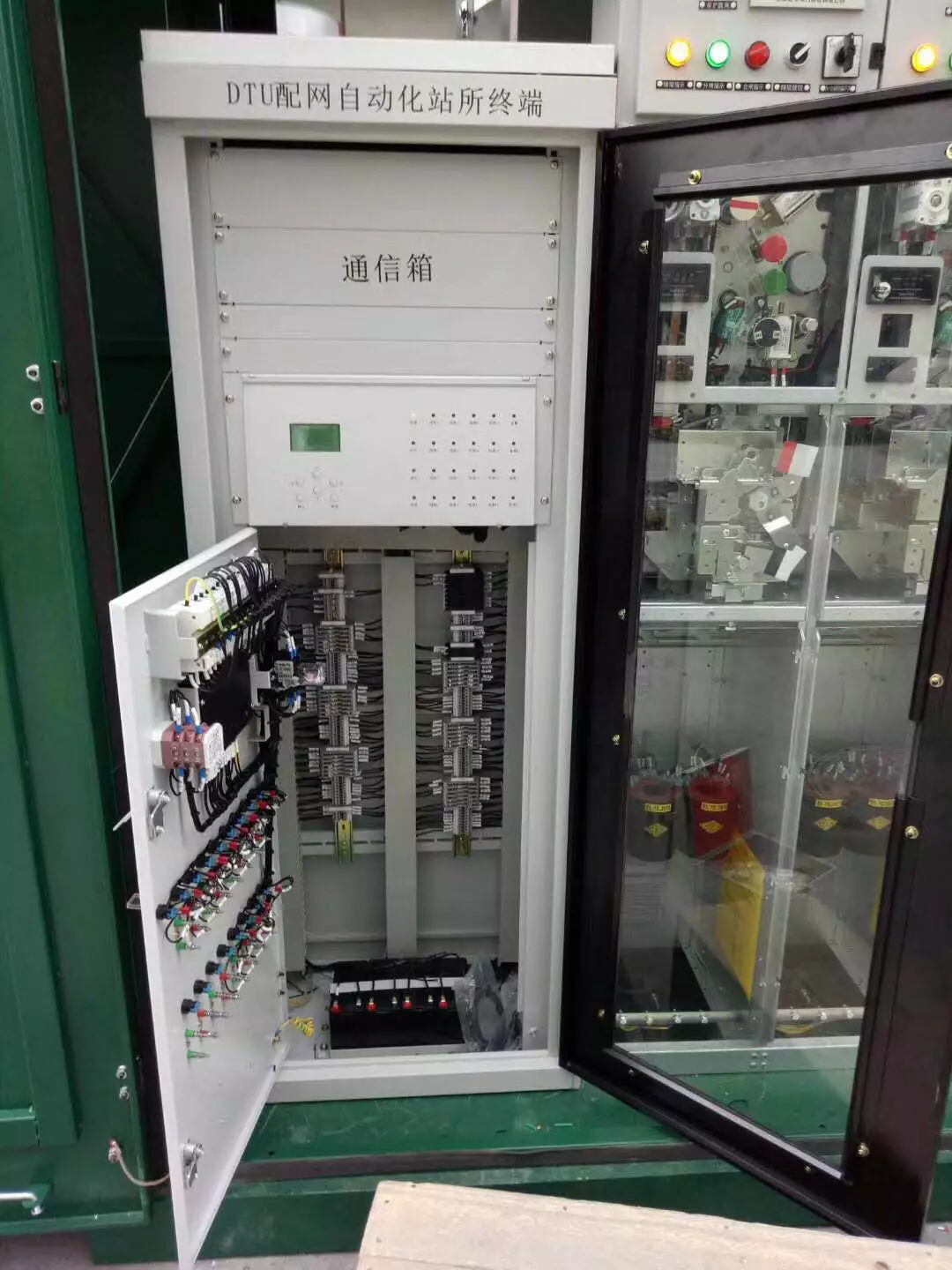
DTUs are generally installed in conventional switching stations, outdoor small switching stations, ring network cabinets, small substations, and box-type substations. They collect and calculate data such as position signals, voltage, current, active power, reactive power, power factor, and electric energy of switching equipment, perform on/off operations on switches, identify and isolate faults in feeder switches, and restore power to non-fault areas. Some DTUs also have features for protection and automatic switching to backup power.
1.1
Definition
DTUs are generally installed in conventional switching stations, outdoor small switching stations, ring network cabinets, small substations, and box-type substations. They collect and calculate data such as position signals, voltage, current, active power, reactive power, power factor, and electric energy of switching equipment, perform on/off operations on switches, and identify and isolate faults in feeder switches, restoring power to non-fault areas.
1.2
Features
1) The chassis structure adopts a standard 4U half (full) chassis with an enhanced design;
2) Uses a rear plug-and-play wiring method, with a fully enclosed design;
3) First adopts an intelligent plug-in solution based on the CANBUS bus, greatly reducing wiring between plug-ins and completely avoiding the risk of poor contact, ensuring high reliability of device operation;
4) The use of intelligent plug-in solutions standardizes the motherboard, facilitating production and on-site maintenance;
5) Ensures that different types of plug-ins cannot be interchanged during structural design, enhancing overall safety;
6) Adopts a 32-bit floating-point SP, with advanced system performance;
7) Uses a 16-bit A/D conversion chip for high sampling accuracy;
8) Employs large-scale programmable logic chips, reducing peripheral circuits and improving reliability;
9) Large-capacity memory design allows for complete field demand for message and incident recording;
10) Uses multilayer printed circuit boards and SMT surface mount technology, providing strong anti-interference performance;
11) Measurement circuit accuracy is automatically calibrated by software, eliminating the need for debugging and reducing on-site inspection and maintenance time;
12) Exceptional electromagnetic compatibility, capable of adapting to harsh working environments;
13) Powerful PC support tools with comprehensive and flexible analysis software for incident analysis;
14) A simple and reliable protection processing system (DSP) combined with a mature real-time multitasking operating system ensures functional reliability while meeting real-time requirements for network communication and human-machine interfaces;
15) Supports various communication interfaces such as RS232/RS485, Ethernet, etc., with built-in Ethernet for simple and reliable engineering applications;
16) Supports standards such as IEC60870-5-101, IEC60870-5-103, IEC60870-5-104;
17) Each device has an independent power-off retention clock system and GPS timing system with time pulse.
1.3
Functions
Remote Measurement
(1) AC electrical measurement
Ia, Ib, Ic, In, Uab, Ucb, Ua, Ub, Uc, Un, etc., in any combination, generally Uab and Ucb are taken on both sides of the switch to monitor the power supply situation at both ends of the feeder.
(2) Using two-meter or three-meter methods, software calculates P, Q, Pa, Pb, Pc, f, cos∮, etc., and uploads as required by the master station;
(3) Protection records of Ia and Ic are uploaded;
(4) DC analog quantities: two channels, battery voltage, temperature, etc.
Remote Signaling
(1) Switch status signals, SOE;
(2) Switch energy storage signals, operation power supply;
(3) Pressure signals, etc.;
(4) Low battery voltage alarms;
(5) Protection actions and abnormal signals;
(6) Other status signals.
Remote Control
(1) Switch on/off, can perform more than two on/off operations after power failure;
(2) Battery maintenance;
(3) Remote recovery of protection signals;
(4) Other remote controls.
Data Transmission Function
Can communicate with the upper station, sending collected and processed information upwards and receiving control commands from the upper station.
Time synchronization with the upper station.
Forwarding information from other terminals upwards.
Forwarding electric energy information upwards.
Proactively uploading incident information (optional function).
Has a local maintenance communication interface.
Communication protocols: Supports multiple communication protocols such as DL/T 634.5101-2002 (IEC60870-5-101), DL/T634.5104-2002 (IEC60870-5-104), DL/T 451-91 cyclic remote communication protocol, DNP3.0, SC1801, MODBUS, etc., and can be expanded as needed.
Communication interfaces: RS-232/485, industrial Ethernet, CAN.
Communication channels: Supports various communication forms such as fiber optics, carrier, wireless spread spectrum, wireless data transmission radio, CDMA, GPRS, and ADSL, which can be selected by the user.
Fault Identification, Isolation, Recovery of Power Supply, and Protection
Equipped with fast-break, delayed overcurrent (complex low voltage) protection, and reclosing functions, selected according to the feeder automation plan.
Monitors fault currents, records overcurrent time, maximum overcurrent value, and reports to the distribution electronic station and distribution master station.
The distribution electronic station and distribution master station judge fault areas based on overcurrent fault information and switch trip information reported by each DTU, generating fault isolation command sequences and non-fault area power restoration command sequences according to the dissipative topological model of the distribution network structure. Automatically or interactively issued for execution.
Local Operation
DTUs have on/off buttons for local operation.
Equipped with local/remote control selection switches, maintenance discharge buttons, etc.
Ring Network Function
When the DTU is set as a connection switch, it automatically controls the switch on/off based on the power supply status of one side or both sides of the PT according to the set values. When both sides of the switch have power, closing the connection switch is prohibited. If networking is required, special settings and confirmations must be made by the master station. When one side loses power, according to the FA plan and settings from the master station, if automatic closing is allowed, it will automatically control the closing to quickly restore power supply.
Setting and Uploading Function
Fast-break setting values, enabling;
Overcurrent setting values, time constants, enabling;
Reclosing time, enabling;
Ring network function settings, cancellation.
Local Maintenance Function
Using the standard communication maintenance interface on the DTU, debugging and maintenance can be performed with dedicated maintenance software.
Includes parameter setting configuration, inspections; remote measurement, remote signaling, remote control, time synchronization testing; data uploading, communication, etc.
Self-Diagnosis and Self-Recovery Function
Has self-diagnostic functions; when abnormalities in the DTU’s memory, clock, I/O, etc., are detected, they are immediately recorded and reported.
Has power-on self-recovery function.
Power UPS and Battery Maintenance Function
Meets the power supply requirements for operating mechanisms, terminal devices, and communication devices.
DTUs are powered by dual power sources, allowing continued operation even if one power source fails.
Normally powered by the main power supply while floating charging the battery. After both power sources fail, the battery provides power, allowing the DTU to continue operating for 24 hours (excluding the radio station).
Low battery voltage alarm protection function.
Automatic battery maintenance: Within a specified time, the dispatcher issues a battery maintenance command, the battery begins to discharge, and when the battery voltage is low, it automatically stops discharging, switches to power from the main supply, and charges the battery. Charging uses constant voltage limited current to ensure safety.
2. Feeder Terminal Equipment (FTU)
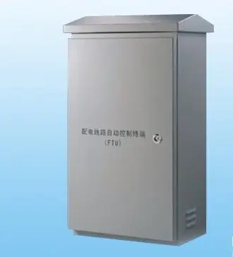
FTU is a switch monitoring device installed next to the feeder switch. These feeder switches refer to outdoor pole-mounted switches, such as circuit breakers, load switches, and sectional switches on 10kV lines. Generally, one FTU is required to monitor one pole-mounted switch, mainly because pole-mounted switches are often installed in a dispersed manner; in cases of shared poles, one FTU can monitor two pole-mounted switches.
2.1
Definition
FTU is a switch monitoring device installed next to the feeder switch. These feeder switches refer to outdoor pole-mounted switches, such as circuit breakers, load switches, and sectional switches on 10kV lines. Generally, one FTU is required to monitor one pole-mounted switch, mainly due to the dispersed installation of pole-mounted switches; in cases of shared poles, one FTU can monitor two pole-mounted switches.
2.2
Features
FTUs use advanced DSP digital signal processing technology, multi-CPU integration technology, and high-speed industrial network communication technology, employing an embedded real-time multitasking operating system, which ensures strong stability, high reliability, good real-time performance, wide environmental adaptability, and powerful functionality. It is a new generation of feeder automation remote terminal device integrating remote measurement, remote signaling, remote control, protection, and communication functions. It is suitable for automation projects in urban, rural, and enterprise distribution networks, completing monitoring, control, and protection of ring network cabinets and pole-mounted switches, as well as other automation functions. It works with distribution electronic stations and master stations to enable normal monitoring of distribution lines and fault identification, isolation, and restoration of non-fault segments.
2.3
Functions
Remote Measurement
(1) AC electrical measurement
Ia, Ib, Ic, In, Uab, Ucb, Ua, Ub, Uc, Un, etc., in any combination, generally Uab and Ucb are taken on both sides of the switch to monitor the power supply situation at both ends of the feeder.
(2) Using two-meter or three-meter methods, software calculates P, Q, Pa, Pb, Pc, f, cos∮, etc., and uploads as required by the master station;
(3) Protection records of Ia and Ic are uploaded;
(4) DC analog quantities: two channels, battery voltage, temperature, etc.
Remote Signaling
(1) Switch status signals, SOE;
(2) Switch energy storage signals, operation power supply;
(3) Pressure signals, etc.;
(4) Low battery voltage alarms;
(5) Protection actions and abnormal signals;
(6) Other status signals.
Remote Control
(1) Switch on/off, can perform more than two on/off operations after power failure;
(2) Battery maintenance;
(3) Remote recovery of protection signals;
(4) Other remote controls.
Data Transmission Function
Can communicate with the upper station, sending collected and processed information upwards and receiving control commands from the upper station.
Time synchronization with the upper station.
Forwarding information from other terminals upwards.
Forwarding electric energy information upwards.
Proactively uploading incident information (optional function).
Has a local maintenance communication interface.
Communication protocols: Supports multiple communication protocols such as DL/T 634.5101-2002 (IEC60870-5-101), DL/T634.5104-2002 (IEC60870-5-104), DL/T 451-91 cyclic remote communication protocol, DNP3.0, SC1801, MODBUS, etc., and can be expanded as needed.
Communication interfaces: RS-232/485, industrial Ethernet, CAN.
Communication channels: Supports various communication forms such as fiber optics, carrier, wireless spread spectrum, wireless data transmission radio, CDMA, GPRS, and ADSL, which can be selected by the user.
Fault Identification, Isolation, Recovery of Power Supply, and Protection
Equipped with fast-break, delayed overcurrent (complex low voltage) protection, and reclosing functions, selected according to the feeder automation plan.
Monitors fault currents, records overcurrent time, maximum overcurrent value, and reports to the distribution electronic station and distribution master station.
The distribution electronic station and distribution master station judge fault areas based on overcurrent fault information and switch trip information reported by each FTU, generating fault isolation command sequences and non-fault area power restoration command sequences according to the dissipative topological model of the distribution network structure. Automatically or interactively issued for execution.
Local Operation
FTUs have on/off buttons for local operation.
Equipped with local/remote control selection switches, maintenance discharge buttons, etc.
Ring Network Function
When the FTU is set as a connection switch, it automatically controls the switch on/off based on the power supply status of one side or both sides of the PT according to the set values. When both sides of the switch have power, closing the connection switch is prohibited. If networking is required, special settings and confirmations must be made by the master station. When one side loses power, according to the FA plan and settings from the master station, if automatic closing is allowed, it will automatically control the closing to quickly restore power supply.
Setting and Uploading Function
Fast-break setting values, enabling;
Overcurrent setting values, time constants, enabling;
Reclosing time, enabling;
Ring network function settings, cancellation.
Local Maintenance Function
Using the standard communication maintenance interface on the FTU, debugging and maintenance can be performed with dedicated maintenance software.
Includes parameter setting configuration, inspections; remote measurement, remote signaling, remote control, time synchronization testing; data uploading, communication, etc.
Self-Diagnosis and Self-Recovery Function
Has self-diagnostic functions; when abnormalities in the FTU’s memory, clock, I/O, etc., are detected, they are immediately recorded and reported.
Has power-on self-recovery function.
Power UPS and Battery Maintenance Function
Meets the power supply requirements for operating mechanisms, terminal devices, and communication devices.
FTUs are powered by dual power sources, allowing continued operation even if one power source fails.
Normally powered by the main power supply while floating charging the battery. After both power sources fail, the battery provides power, allowing the FTU to continue operating for 24 hours (excluding the radio station).
Low battery voltage alarm protection function.
Automatic battery maintenance: Within a specified time, the dispatcher issues a battery maintenance command, the battery begins to discharge, and when the battery voltage is low, it automatically stops discharging, switches to power from the main supply, and charges the battery. Charging uses constant voltage limited current to ensure safety.
3. Distribution Transformer Terminal Equipment (TTU)
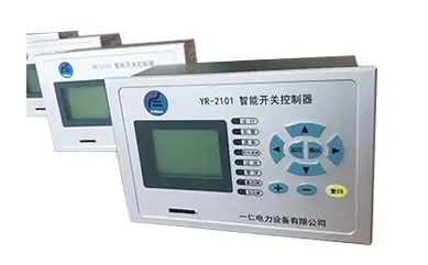
TTU monitors and records the operating conditions of distribution transformers. Based on the sampled values of three-phase voltage and current on the low voltage side, it calculates the effective voltage, effective current, active power, reactive power, power factor, active energy, and reactive energy every 1 to 2 minutes, recording and saving these values for a period (one week or one month) as well as the hourly values of the above arrays for typical days, including the maximum and minimum voltage and current values and their occurrence times, power interruption times, and recovery times. The recorded data is stored in the device’s non-volatile memory, ensuring that the content is not lost when the device is powered off. The distribution master station reads the TTU measurement values and historical records regularly through the communication system to promptly identify issues such as transformer overload and power outages. Based on the recorded data, it analyzes voltage compliance rates, power supply reliability, and load characteristics, providing fundamental data for load forecasting, distribution network planning, and incident analysis. If communication conditions are not available, a handheld computer can be used to read the records on-site every week or month and later transfer them to the distribution master station or other analysis systems. The TTU has a similar structure to the FTU, but since it only has data collection, recording, and communication functions without control functions, its structure is much simpler. To simplify design and reduce costs, the TTU is powered directly by the low voltage side of the transformer without a battery. If there is a reactive power compensation capacitor bank on-site, to avoid redundant investment, the TTU must add capacitor switching control functions.
3.1 Definition
TTU monitors and records the operating conditions of distribution transformers. Based on the sampled values of three-phase voltage and current on the low voltage side, it calculates the effective voltage, effective current, active power, reactive power, power factor, active energy, and reactive energy every 1 to 2 minutes, recording and saving these values for a period (one week or one month) as well as the hourly values of the above arrays for typical days, including the maximum and minimum voltage and current values and their occurrence times, power interruption times, and recovery times. The recorded data is stored in the device’s non-volatile memory, ensuring that the content is not lost when the device is powered off. The distribution master station reads the TTU measurement values and historical records regularly through the communication system to promptly identify issues such as transformer overload and power outages. Based on the recorded data, it analyzes voltage compliance rates, power supply reliability, and load characteristics, providing fundamental data for load forecasting, distribution network planning, and incident analysis. If communication conditions are not available, a handheld computer can be used to read the records on-site every week or month and later transfer them to the distribution master station or other analysis systems.
3.2 Features
Suitable for monitoring and measuring electric energy of distribution transformers ranging from 100 to 500 KVA for power supply companies, county-level power companies, power plants, industrial and mining enterprises, military academies, and rural electric management stations. It assists in line loss assessment through electricity monitoring and can also transmit all data to the electricity management center via GPRS communication network, providing the most accurate and real-time decision-making basis for optimizing low voltage distribution networks.
3.3 Functions
■ “Four-in-One” Comprehensive Function
Integrates four functions: measurement, power quality monitoring, distribution transformer condition monitoring, and reactive power compensation.■ Intelligent Reactive Power CompensationIntelligent capacitors can form their own system, automatically switching on and off for reactive power compensation.■ Flexible NetworkingFollows the current distribution transformer monitoring system protocols of the State Grid Corporation and the Southern Power Grid Company, facilitating integration into existing load management systems and distribution management systems of power enterprises, providing complete real-time voltage and reactive information, and can also independently form a real-time reactive information system.■ Simple EngineeringThe device structure is simple, with fewer and clearer internal connections, and modular capacitor assembly for easy installation, maintenance, and adjustment of compensation capacity.
4. Remote Terminal Unit (RTU)
4.1 Definition
RTU (Remote Terminal Unit) is a remote measurement and control unit responsible for monitoring and controlling field signals and industrial equipment. Compared to commonly used programmable logic controllers (PLCs), RTUs typically have excellent communication capabilities and larger storage capacities, suitable for harsher temperature and humidity environments, and provide more computational functions. Due to the comprehensive functionality of RTUs, they are widely used in SCADA systems.
Remote terminal devices (RTUs) are electronic devices installed at remote sites to monitor and measure sensors and equipment located at those sites. RTUs convert the measured status or signals into a data format that can be transmitted over communication media. They also convert data sent from the central computer into commands to control the functions of the equipment.
4.2 Features
(1) Long communication distance;
(2) Used in various harsh industrial environments;
(3) Modular structured design for easy expansion;
(4) Widely used in industries such as water conservancy, power dispatching, and municipal dispatching, which involve remote signaling, measurement, and control.
4.3 Functions
(1) Collects status quantities and sends them to the remote location, with optical isolation and priority for remote signaling;
(2) Collects data quantities and sends them to the remote location, with optical isolation;
(3) Directly collects system frequency electrical quantities, measuring voltage, current, active, and reactive power, and sends them to the remote location, capable of calculating forward and reverse electric quantity;
(4) Collects pulse electric quantities and sends them to the remote location, with optical isolation;
(5) Receives and executes remote control and returns signals;
(6) Program self-restoration;
(7) Device self-diagnosis (fault diagnosis down to the plug-in level);
(8) Device self-tuning;
(9) Channel monitoring;
(10) Receives and executes remote tuning;
(11) Receives and executes time synchronization commands (including optional GPS time synchronization function);
(12) Communicates with two or more master stations;
(13) Collects event sequence records and sends them to the remote location;
(14) Provides multiple digital interfaces and multiple analog interfaces;
(15) Allows remote/local setting of characteristics for each interface;
(16) Provides multiple communication protocols; each interface can transmit data of different protocols based on remote/local settings;
(17) Accepts remote commands and selects which types of information to send;
(18) Can forward multiple substation remote information;
(19) Local display function, with local interface having isolators;
(20) Supports communication with devices using spread spectrum, microwave, satellite, carrier, etc.;
(21) Optional and multiple protocols can run simultaneously, such as DL451-91 CDT protocol, while also supporting POLLING protocols and other international standard protocols (such as DNP3.0, SC1801, 101 protocol);
(22) Can be remotely configured through telecommunications networks and power system channels.
Main differences: DTU is a client connected via SOCKET. Therefore, DTU alone cannot complete wireless data transmission and requires the cooperation of background software. FTU and RTU have the following differences: FTU is smaller in size, more numerous, can be placed outdoors on feeders, equipped with transmitters, directly sampling AC, resistant to high temperatures, cold-resistant, and suitable for harsh outdoor environments; while RTU is installed indoors and has higher environmental requirements; FTU collects smaller data quantities, requires lower communication speeds, and has higher reliability requirements; while RTU collects larger data quantities, requires higher communication speeds, and has higher reliability requirements with dedicated channels. TTU is a single-function unit that only collects and controls information related to distribution transformers.
(Source: Power Knowledge Classroom)
『This article is copyrighted by the original author. If there is any infringement, please contact for removal.』
Editor: Hu Ying
Proofreader: Duan Shaomin
Reviewer: Li Guoqing