The PCS-978 series digital transformer protection is suitable for voltage levels of 35kV and above, requiring dual sets of main protection and dual sets of backup protection with various wiring methods for transformers.The PCS-978 device supports both electronic and conventional current transformers, complies with the power industry communication standard DL/T667-1999 (IEC60870-5-103) and the new generation substation communication standard IEC61850, supports GOOSE input and output functions, and supports distributed protection configuration mode.The PCS-978 includes two chassis structures: 4U and 8U. When using conventional current transformers, the 4U chassis device can input a maximum of 36 analog signals, meeting the requirements of most transformer protection devices, while the 8U chassis can input a maximum of 84 analog signals, suitable for special transformer protection requirements.PCS978 ConfigurationThe PCS-978 device can provide all the electrical protection required for a transformer, with main and backup protection sharing the same TA. These protections include:Longitudinal steady-state ratio differential, longitudinal differential instantaneous, longitudinal frequency variation ratio differential, phase difference steady-state ratio differential protection, low voltage side differential protection, phase-side ratio differential protection, zero-sequence ratio differential protection, over-excitation protection, composite voltage lockout directional overcurrent, inter-phase impedance protection, ground impedance protection, zero-sequence directional overcurrent, zero-sequence overvoltage, gap zero-sequence overcurrent, failure interlocking, simple bus differential.
Typical Application Configuration of PCS-978GE
Three-winding transformer configuration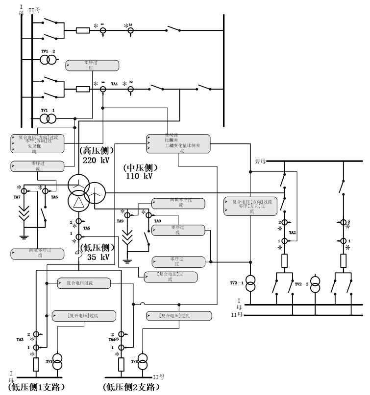 Auto-transformer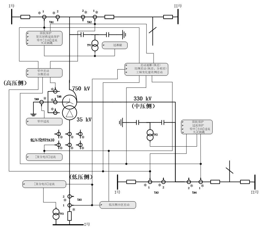
PCS978 Hardware System
PCS978 General Hardware Module Diagram Power Module (NR1301)
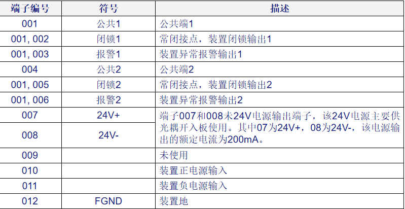
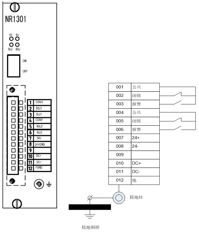 Note: The rated input voltage of the power supply is 220V and 110V adaptive; other voltage levels need to be specially ordered. Please check that the rated input voltage of the supplied power module matches the control power voltage before commissioning.Note: The power module provides terminals 012 and grounding posts for grounding the device. Terminal 012 should be connected to the grounding post and then connected to the grounding bus of the cabinet through a dedicated grounding wire.
 CPU Module (NR1101)
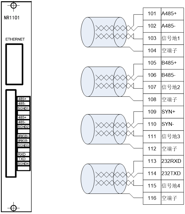 The CPU module is the second module of this device, slot number 1.The CPU module consists of a high-performance embedded processor, FLASH, SRAM, SDRAM, Ethernet controller, and other peripherals. It manages the entire device, including human-machine interface, communication, and waveform recording functions.The CPU module receives data from other modules in the device via the internal bus and communicates with the LCD panel via the RS-485 bus. This module has 2 100BaseT Ethernet interfaces, 2 RS-485 external communication interfaces, PPS/IRIG-B differential time synchronization interface, and RS-232 printer interface.DSP Module (NR1151, NR1152, NR1136)The DSP module consists of a high-performance digital signal processor, fiber optic interface, synchronized sampling 16-bit high-precision ADC, and other peripherals. The module performs analog data acquisition, protection logic computation, and trip output functions.When connected to conventional current transformers, the module synchronizes data acquisition via the AC input board; when connected to electronic current transformers, it receives synchronized sampling data in real-time from the merging unit via multimode fiber optic interface.The NR1151 DSP module performs protection computation and protection startup functions, as well as measurement and control functions for metering and control.The NR1152 DSP module supports FT data reception function as per 60044-8.The NR1137 DSP module supports GOOSE and SMV sampling functions.
PCS978 Differential Protection
Steady-state low-value ratio differential relayAction equation: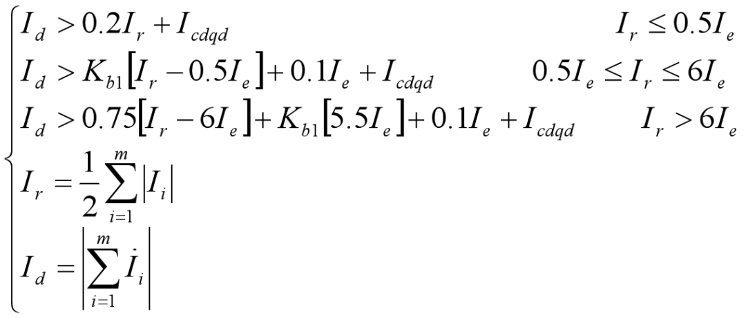 Rated current on each side:
 The setting values for the differential startup value and ratio coefficient are:
 Substituting into the differential equation gives (all quantities converted to per unit value):
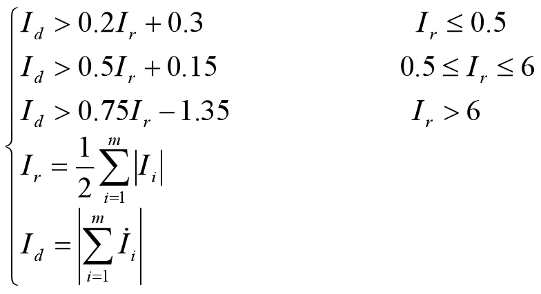 From the above formula, it can be seen that the differential equation consists of three linear segments, with slopes of 0.2, 0.5, and 0.75.
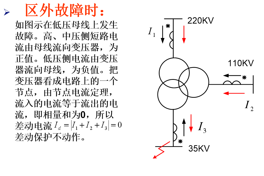
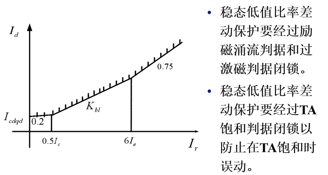 The unbalanced current in differential protectionTransformer differential protection differs from line differential protection in that the unbalanced current in transformer differential protection is much larger than that in line differential protection, thus raising concerns about the sensitivity and reliability of transformer differential protection. The causes of unbalanced current in transformer differential protection mainly include the following:1. Steady-state unbalanced current (1) Due to different models of current transformers on each side, the saturation characteristics and excitation currents of the current transformers differ, leading to unbalanced current. It must meet the 10% error curve requirement of the current transformer. (2) Unbalanced current caused by differences between the actual transformation ratio of the current transformers and the calculated transformation ratio. (3) Unbalanced current caused by changing the transformer tap. (4) Unbalanced current caused by over-excitation during transformer operation.2. Transient unbalanced current (1) Unbalanced current caused by the non-periodic component of short-circuit current, primarily due to the excitation current of the current transformers, which saturates the core, increasing error. (2) Excitation inrush current at transformer no-load closing, with current only on one side of the transformer.The differential equation of the three-segment line In the three-segment ratio braking characteristic, the current startup value is aimed at the unbalanced current during normal operation, so it should avoid the unbalanced current under maximum load conditions, usually taken as Icdqd= (0.2 to 0.5)IN. The characteristic of using three-segment ratio differential is that it reflects the actual situation during a fault. In the case of smaller external faults, Ie= (2 to 3)IN, the saturation degree of the current transformers is not deep, and the error is still small. At this time, a smaller braking coefficient (Kbl=0.2 to 0.5) is allowed, thus increasing the action area and improving sensitivity during faults within this area. In the case of larger external faults, a larger braking coefficient (Kbl=0.75) can be chosen, as the current transformers pass through a large transient fault current, deepening saturation and increasing error. A larger braking coefficient should be selected, and under these conditions of short-circuit current within this area, the differential current is much greater than the braking current, ensuring reliable operation of protection during faults within this area.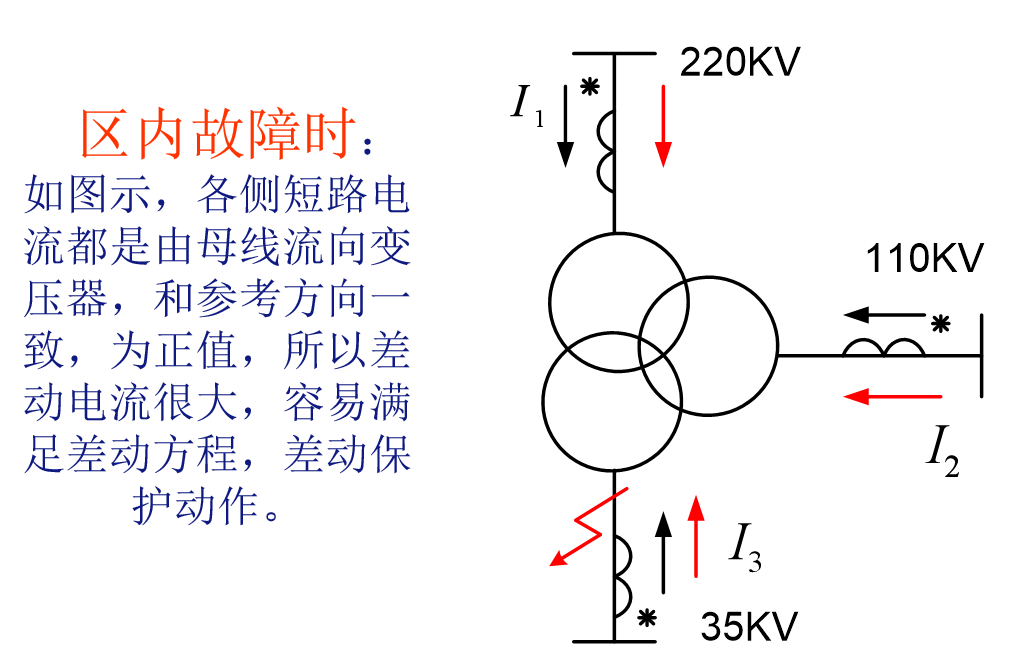
 The TA saturation problem in differential protection
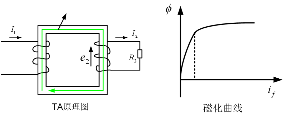 After the primary winding carries the excitation current, a magnetic flux is generated in the core, with the magnetization curve shown on the right. When the excitation current is not large, the magnetic circuit is not saturated, and there is a linear relationship between magnetic flux and excitation current. The magnetic flux induces current I2 in the secondary winding, and the TA measurement is accurate.When the primary excitation current is relatively large, the magnetic circuit saturates, the magnetic flux becomes a flat-top wave, and the rate of change of magnetic flux is very small, approaching zero. According to electromagnetic induction law:
 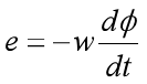 The induced potential in the secondary winding is proportional to the rate of change of magnetic flux, so the potential in the secondary winding approaches zero, and the current also approaches zero. This is TA saturation.TA saturation waveform
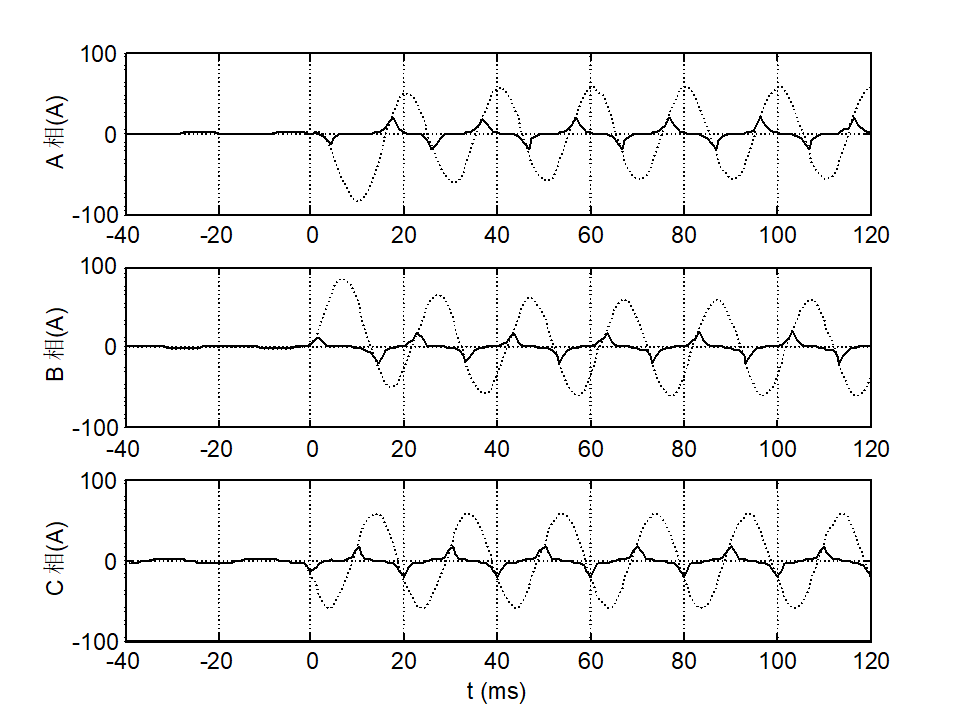 Main characteristics of severe TA saturation1) The secondary current waveform has severe distortion and is significantly non-sinusoidal.2) After a short circuit, the TA quickly enters deep saturation, causing the induced electromotive force of the secondary winding to drop to zero. For a corresponding period, the secondary current is zero, during which the primary current becomes entirely excitation current.3) After the primary current becomes entirely excitation current, as its instantaneous value decreases, the TA gradually exits saturation. When it drops to zero and then changes polarity, the core safely exits saturation, the induced electromotive force in the secondary winding increases, and the secondary current becomes almost equal to the primary current, but at this time, there is still considerable residual magnetism in the core.4) When the primary current returns to its initial polarity and rises, due to the presence of residual magnetism, the core quickly saturates again, and the secondary current drops to zero.5) At the start of the short circuit, the core must maintain the magnetic flux constant, or the inductance of the excitation circuit does not allow its current to change suddenly; the primary current transforms entirely into secondary current, and the TA has no error. Although this period is short, generally 3-8ms, it can be utilized by differential protection.
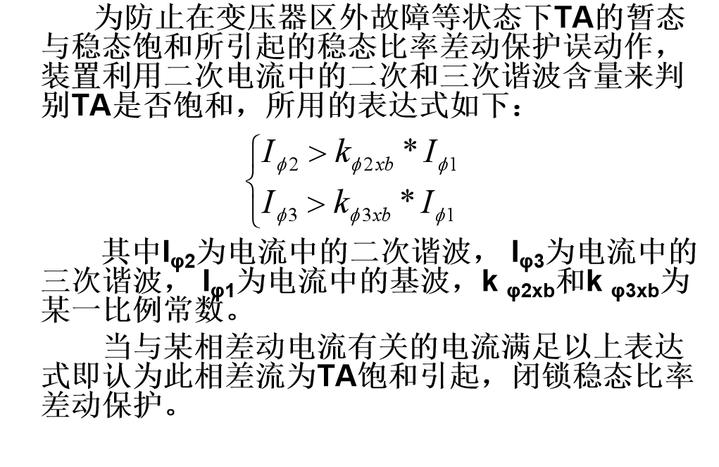
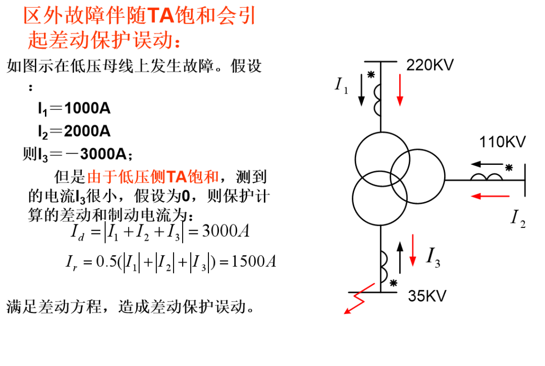 TA saturation handling methods
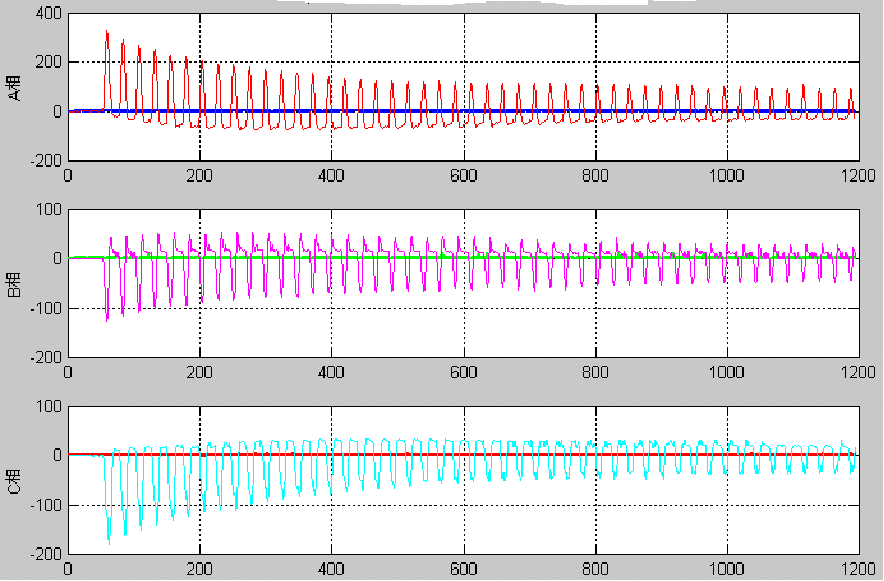
 The excitation inrush current problem in differential protectionDuring normal operation, the excitation current is relatively small, generally not exceeding 3% of the rated current, but in: (1) Transformer no-load closing (vacuum throw) (2) After the removal of external faults, when voltage recoversIn these two cases, a large excitation current may occur. Characteristics of excitation inrush current waveform: ① The maximum amplitude of excitation inrush current is very large, possibly reaching 5-10 times the rated current of the transformer. The smaller the transformer capacity, the larger this multiple. ② There is a large non-periodic component. The waveform is skewed to one side of the time axis, thus the waveform is severely asymmetric. ③ There are a large number of harmonic components, especially the second harmonic component is significant. The ratio of the second harmonic to the fundamental component I2/I1 is generally greater than 0.15. ④ The waveform shows discontinuities, with the discontinuity angle α generally greater than 60°. The waveform of excitation inrush current is related to the phase of the closing moment voltage, the size and direction of the residual magnetism in the core, the capacity of the power supply and transformer, the properties of the core material and magnetization curve, the saturation magnetic density of the transformer, and the impedance and time constant of the closing circuit. If the voltage reaches its maximum value at the moment of closing, there will be no non-periodic magnetic flux, and thus no excitation inrush current, only the normal excitation current. If the voltage is zero at the moment of closing, the excitation inrush current is maximized. Therefore, in a three-phase transformer, the excitation inrush current of the three phases is different. Considering that the three-phase voltages of the power supply differ by 120° during transformer no-load throw, at least two phases will experience varying degrees of excitation inrush current regardless of when the closing occurs.Transformer no-load excitation inrush current recording
 The identification of excitation inrush current uses the principles of harmonic braking and waveform asymmetry. After being identified as inrush current, phase locking is applied.The principle of harmonic braking. The ratio of the second and third harmonic components in the differential current Id to the fundamental component is used as the criterion for locking the differential.When satisfied:
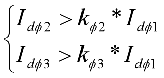 Phase locking differential protection.Using waveform distortion to identify excitation inrush current
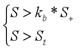 S is the full-cycle integral value of the differential currentS+ is the full-cycle integral value of “the instantaneous value of the differential current + the instantaneous value of the differential current half a cycle ago”.kb is a certain fixed constantSt is the threshold setting valueThe device identifies the excitation inrush current and locks that corresponding ratio differential element.
(Source: Power Knowledge Classroom Image Source: Power Knowledge Classroom)
『This article is copyrighted by the original author. If there is any infringement, please contact for deletion.』
Editor: Hu Ying
Proofreader: Shi Haijiang
Reviewer: Chang Haibo
含分布式储能的区域电网多时间尺度优化调度策略电力系统储能应用场景研究综述规模化新能源-储能技术控制策略及商业模式研究收藏丨变压器中性点保护讲解收藏丨低压配电系统接线形式剖析收藏丨10kV高压开关柜柜体设计注意要点!收藏丨变配电室高度如何确定?

视频号推荐
-扫码关注-
欢迎加电小淘好友,各种专业群可加哦!