1. Introduction to CAN
In automotive electronics, there are many ECU control modules that manage different functions. To enable these numerous ECU modules to work together, the CAN protocol was developed, allowing multiple ECU modules to be connected to the CAN bus for local area network communication between ECUs.
CAN is a serial communication protocol that supports multi-master communication, where all nodes (ECUs) can actively send data without relying on a central controller. It employs a non-destructive arbitration mechanism that resolves bus conflicts through ID priority, ensuring that high-priority data is transmitted first. The bus is highly reliable, with built-in CRC checks, error detection, and recovery mechanisms, while also using differential signaling to enhance resistance to electromagnetic interference. The CAN bus achieves cost advantages by simplifying wiring and reducing system complexity.

2. CAN Hardware Connection
CPU with Built-in CAN Controller

**CPU without CAN Controller**

The CAN bus has 120-ohm termination resistors at both ends to eliminate signal reflections on the bus.
As shown in the above diagram, there is no clock line in the CAN hardware connection, indicating that it is an asynchronous connection and cannot perform simultaneous receiving or sending, which means it is half-duplex communication.
3. CAN Signal Levels
CAN_H: High-level signal line, typically with a voltage range of 2.5V to 3.5V.
CAN_L: Low-level signal line, typically with a voltage range of 1.5V to 2.5V.
Recessive state (logic “1”): When the voltages of CAN_H and CAN_L are equal (usually 2.5V), it indicates that the bus is in an idle state. At this time, there is no data transmission on the bus, and all devices are waiting for communication. The recessive state is also referred to as **”idle level” or “logic 1″**.
Dominant state (logic “0”): When the voltage difference between CAN_H and CAN_L is 2V, it indicates that data is being transmitted. Specifically, CAN_H is at 3.5V and CAN_L is at 1.5V, indicating logic “0”. The dominant state indicates that the bus is transmitting data and has a higher priority.
The characteristics of differential signaling give the CAN bus strong anti-interference capabilities in noisy environments.
4. CAN Protocol Frame Structure
4.1 What is a Data Frame?
CAN communication sends data through data frames, so the data frame carries data from the sending device to the receiving device.
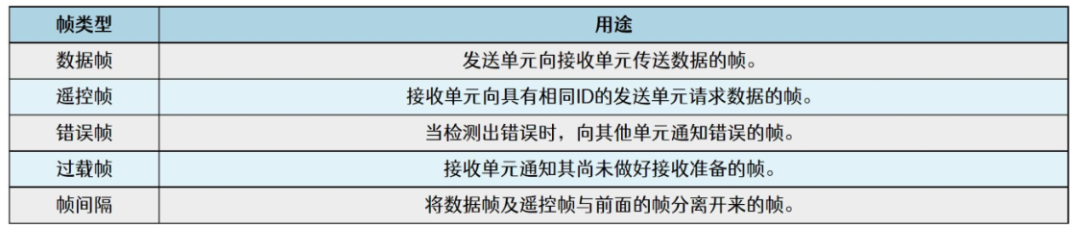
4.2 Types of Frames
4.3 Standard Data Frame
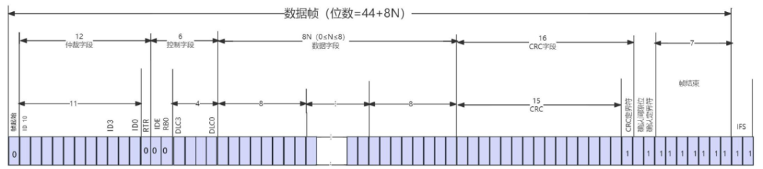
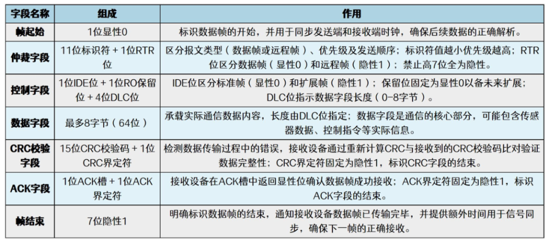
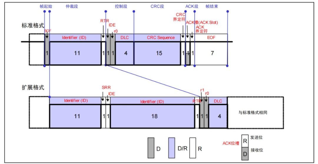
As shown in the above diagram, RTR=0 indicates that this message is a data frame, and IDE=0 indicates that it is a standard data frame. **The arbitration field prohibits the high 7 bits from being recessive to avoid arbitration errors.**
The CAN ACK acknowledgment occurs during data transmission. During the data frame process, when CAN sends data, it releases the bus, which is at a high level. If data is received, it will pull the level low, and after receiving is complete, it releases the level, which is why the CRC and ACK delimiters are both 1.
4.4 Extended Data Frame
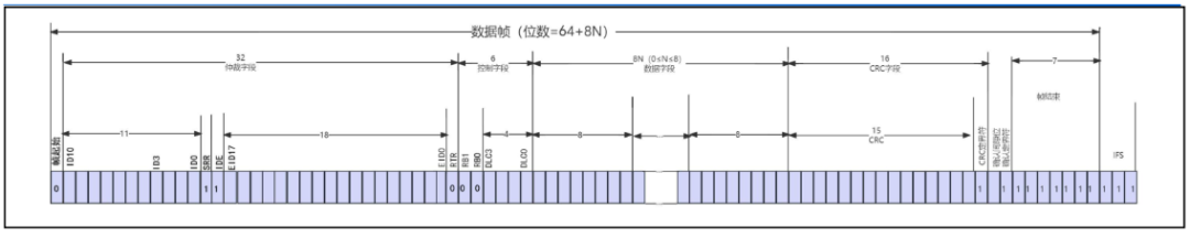
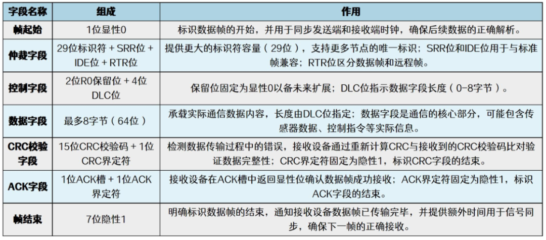
The extended data frame is designed to increase the ID capacity. In the above diagram, note the position of IDE: it follows the original standard data frame’s 11-bit ID and is set to 1, indicating that this frame is an extended frame. There is also an SRR bit (fixed at 1); after the 29-bit ID is completed, the original RTR follows, where RTR=0 indicates it is still a data frame. Additionally, there are two reserved bits (fixed at 0) added at the end.
The role of the SRR bit: The SRR bit in the CAN protocol replaces the RTR bit of the standard frame, located in the arbitration segment of the extended frame. Its purpose is to be forced to a recessive level (1) to ensure that when standard frames and extended frames compete for the bus, the standard frame has a higher priority due to the RTR bit being dominant (0). When both standard and extended frames are sent simultaneously, the bus detects the dominant level (0) through arbitration logic, allowing the standard frame to win.
4.5 Remote Frame
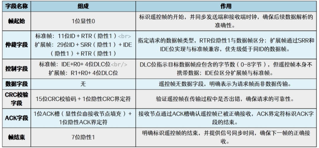
The remote frame is created by removing the data field from the data frame. There are standard and extended remote frames, and it is important to note that the RTR bit of the remote frame is 1.
Pay attention to the position of the extended remote frame’s SSR, which is at a dominant level, ensuring that the priority of the extended remote frame is lower than that of the standard remote frame.
4.6 Error Frame
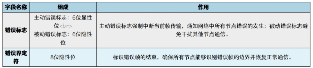
When a device sends an error flag, it may trigger other devices to send error flags as well, so there may be multiple error flags. (Dominant bit: logic 0, recessive bit: logic 1)
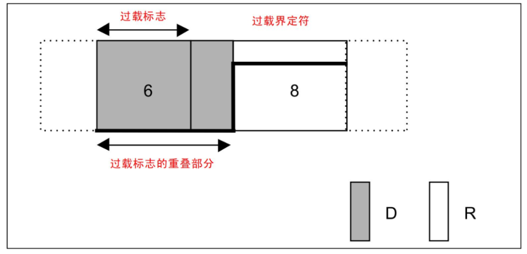
4.7 Overload Frame

4.8 Frame Interval
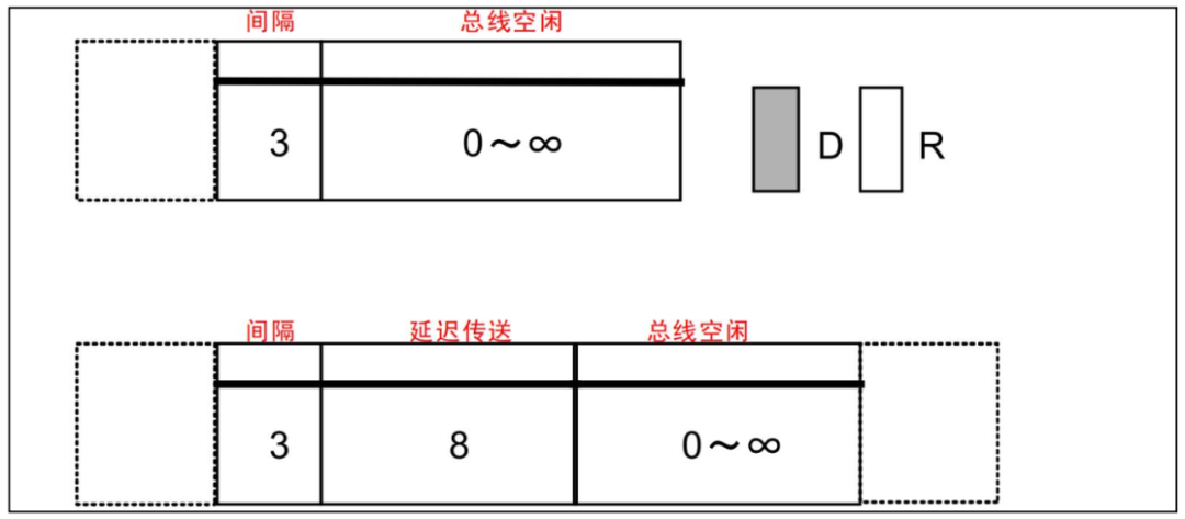
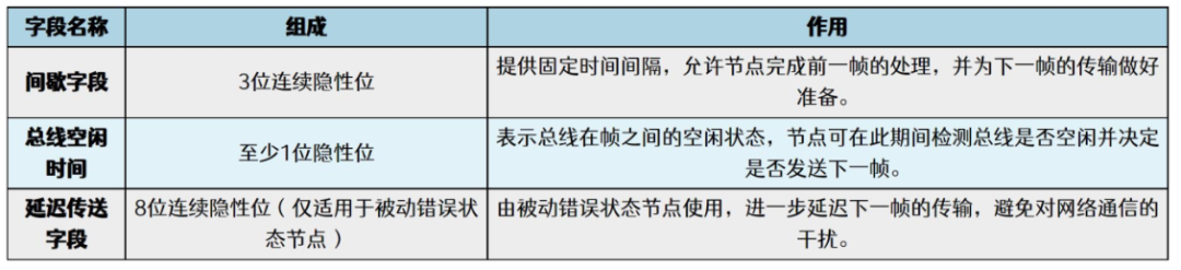
The frame interval is used to separate data frames and remote frames.
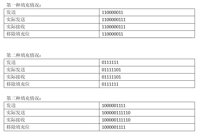
4.9 Bit Stuffing
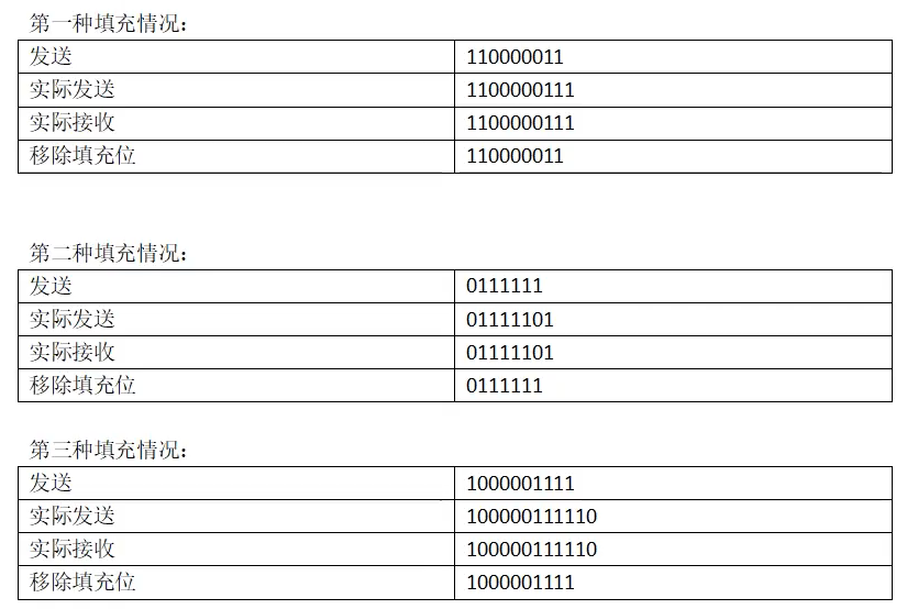
Bit stuffing rule: When there are 5 consecutive bits of the same polarity, a stuffing bit of the opposite polarity is inserted at the 6th bit. This mechanism ensures that there is always a level change on the bus by breaking up long strings of the same level, thus maintaining synchronization between the sender and receiver.
5. Bit Time
Bit time is the time required for a (binary) bit to be transmitted on the bus. One bit time is divided into four segments, which are also referred to as the minimum time unit of TQ.
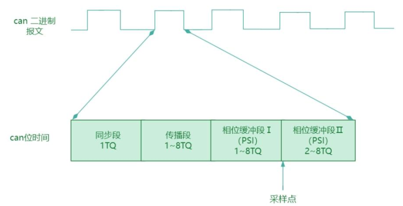

Baud Rate = 1 / Bit Time
The role of bit time: CAN is asynchronous communication, and there is no clock signal line. Each node connected to the same bus network uses a predetermined baud rate for communication. CAN also uses synchronization methods to combat interference, reduce errors, and ensure correct sampling of bus level signals, ensuring normal communication. The main purpose is to adjust the sampling point to be in the middle of the sampled signal.