Abstract
This article discusses the definition of EMC, testing methods for microcontroller application systems, the application of new EMC devices and materials, and troubleshooting techniques. Anyone involved in the research, development, production, or supply of electronic products must conduct EMC electromagnetic compatibility testing.
Introduction
EMC, or Electromagnetic Compatibility, refers to the ability of a device or system to operate correctly in its electromagnetic environment without causing unacceptable electromagnetic interference to anything in that environment. EMC testing includes two main aspects: testing the intensity of electromagnetic interference emitted to ensure compliance with relevant standard limits, and conducting sensitivity tests under specified electromagnetic interference conditions to confirm compliance with relevant standard immunity requirements.
For engineers involved in the design of microcontroller application systems, mastering certain EMC testing techniques is essential. EMC encompasses both electromagnetic interference (EMI) and electromagnetic sensitivity (EMS). Since electrical products can interfere with other devices or be affected by interference from other devices, it not only relates to the reliability and safety of the product but can also impact the normal operation of other devices, potentially leading to safety hazards.
EMC Testing for Microcontroller Systems
(1) Testing Environment
To ensure the accuracy and reliability of test results, electromagnetic compatibility measurements have high requirements for the testing environment, which can include outdoor open areas, shielded rooms, or anechoic chambers.
(2) Testing Equipment
Electromagnetic compatibility measurement equipment is divided into two categories: one for measuring electromagnetic interference, which can measure EMI when connected to appropriate sensors; the other for measuring electromagnetic sensitivity, which simulates different interference sources and applies them to various devices under test using appropriate coupling/decoupling networks, sensors, or antennas for sensitivity or immunity measurements.
(3) Measurement Methods
There are many measurement methods for electromagnetic compatibility testing based on different standards, but they can be summarized into four categories: conducted emission testing, radiated emission testing, conducted immunity testing, and radiated immunity testing.
(4) Testing Diagnosis Steps
Figure 1 illustrates the steps for analyzing electromagnetic interference emissions and faults in a device or system. Following these steps can improve the efficiency of testing diagnostics.
(5) Testing Preparation
① Testing site conditions: The EMC testing laboratory should be an anechoic chamber and a shielded room. The former is used for radiated emission and radiated immunity testing, while the latter is used for conducted emission and conducted immunity testing.
② Environmental level requirements: The electromagnetic environment levels for conducted and radiated emissions should ideally be well below the standard limit values, generally at least 6dB lower than the limit values.
③ Test table.
④ Isolation of measurement equipment and the device under test.
⑤ Sensitivity criteria: Generally provided by the party being tested, monitored and determined through measurement and observation to assess the degree of performance degradation.
⑥ Placement of the device under test: To ensure repeatability of the experiment, there are usually specific regulations regarding the placement of the device under test.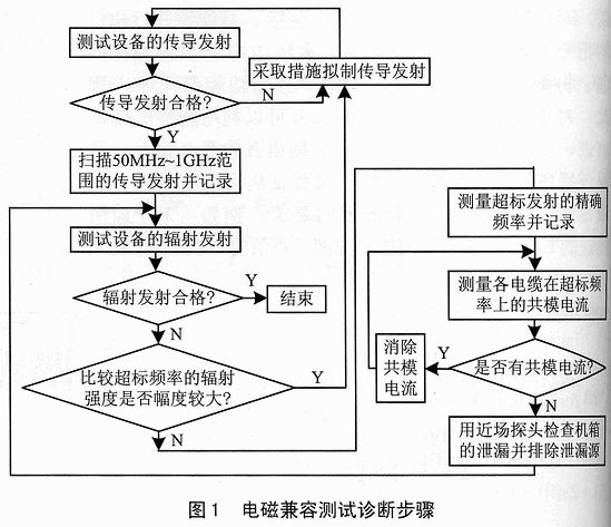 (6) Types of Tests
Conducted emission testing, radiated emission testing, conducted immunity testing, radiated immunity testing.
(7) Common Measurement Instruments
Electromagnetic interference (EMI) and electromagnetic sensitivity (EMS) testing require various electronic instruments, such as spectrum analyzers, electromagnetic field interference measurement instruments, signal sources, amplifiers, oscilloscopes, etc. Due to the wide frequency range of EMC testing (20Hz to 40GHz), large amplitude (from μV to kW), and various modes (FM, AM, etc.), it is crucial to use electronic instruments correctly. The appropriate instrument for measuring electromagnetic interference is the spectrum analyzer. A spectrum analyzer displays the relationship between voltage amplitude and frequency, showing the waveform known as the spectrum. It overcomes the limitations of oscilloscopes in measuring electromagnetic interference, allowing precise measurement of interference intensity at various frequencies and directly displaying the spectrum components of the signal.
When addressing electromagnetic interference issues, the most critical task is to identify the source of the interference. Only by accurately locating the source can effective measures be proposed to mitigate the interference. Determining the source based on the frequency of the signal is the simplest method, as frequency characteristics are the most stable among all signal features, and circuit designers are often well aware of the signal frequencies at various points in the circuit. Therefore, knowing the frequency of the interference signal allows for inferring which part of the circuit is generating the interference. Since the amplitude of electromagnetic interference signals is often much smaller than that of normal operating signals, measuring this with a spectrum analyzer is relatively straightforward. The narrow intermediate frequency bandwidth of the spectrum analyzer allows it to filter out signals that differ from the interference signal frequency, enabling precise measurement of the interference signal frequency and thus identifying the circuit generating the interference signal.
Electromagnetic Compatibility Troubleshooting Techniques
(1) Solutions for Conducted Problems
① Reduce EMI current by connecting a high impedance in series.
② Short-circuit EMI current to ground or other circuit conductors by connecting a low impedance in parallel.
③ Cut off EMI current using current isolation devices.
④ Suppress EMI current through its own action.
(2) Capacitive Solutions for Electromagnetic Compatibility
A common phenomenon is to view one side of the filter capacitor as directly connected to a separate impedance rather than to a transmission line. A typical case occurs when the length of an input/output line reaches or exceeds 1/4 wavelength, making the transmission line appear “long.” This change can be approximately represented by the formula:
l≥55/f
Where: l is in meters, and f is in MHz. This formula considers the average propagation speed, which is 0.75 times that of free space theory.
a. Dielectric materials and tolerances
Most capacitors used for electromagnetic interference filtering are non-polarized capacitors.
b. Differential mode (line-to-line) filtering capacitors.
c. Common mode (line-to-ground/case) filtering capacitors.
Common mode (CM) decoupling typically uses small capacitors (10 to 100nF). Small capacitors can short undesirable high-frequency currents to the case before they enter sensitive circuits or when they are far from noisy circuits. To achieve good high-frequency attenuation, minimizing or eliminating parasitic inductance is key. Therefore, it is necessary to use ultra-short leads, preferably with leadless components.
(3) Inductive, Series Loss Electromagnetic Compatibility Solutions
For capacitors, if Zs and Z1 are not purely resistive, their actual values must be used when calculating frequency. When capacitors are connected in series in power or signal circuits, the following must be satisfied:
① The working current should not cause excessive heating or significant drops in inductance;
② The current should not cause magnetic saturation in inductors, especially for high-permeability materials.
Possible solutions include:
* Magnetic core materials;
* Ferrite and ferrite-loaded cables;
* Inductors, differential mode, and common mode;
* Grounding chokes;
* Combined inductive-capacitive components.
(4) Solutions for Radiated Problems
In many cases, radiated electromagnetic interference issues may arise during the conducted phase and can be mitigated. Some solutions can suppress interference devices in the radiated transmission path, functioning similarly to field shielding. According to shielding theory, the effectiveness of such shielding primarily depends on the frequency of the electromagnetic interference source, the distance to the shielding device, and the characteristics of the electromagnetic interference field—electric field, magnetic field, or plane wave.
① Conductive tape.
Using copper or aluminum tape allows for quick and straightforward establishment of direct shielding and low-resistance connections or buses. They are convenient for both temporary and relatively permanent solutions. Thickness ranges from 0.035 to 0.1mm, with a conductive adhesive on the back for installation. If using copper conductive tape, its resistance is approximately 20mΩ/cm². Applications include electrical shielding enclosures; locating leakage points during failures; as an emergency solution to convert plastic connectors to metal, shielding ordinary flat cables, etc.
② Mesh shielding tape and zippered covers.
Tinned steel mesh tape: primarily used for installation on an already assembled electrical enclosure as an easy-to-install band-type shield. It is an effective solution for reducing magnetic field radiation or sensitivity issues.
Zippered shielding covers: used when there are clear indications that electrical fields are the primary cause of EMI coupling.
③ EMI sealing gaskets.
Applications: EMI sealing gaskets are the most commonly used method for addressing radiated issues, sensitivity issues, ESD, electromagnetic pulses, and TEMPEST issues when the following conditions exist and true SE is required:
* The chassis leakage has been identified as the primary radiated path.
* The mating surfaces are not smooth, flat, or hard enough to provide good contact.
④ EMI shielding for windows and ventilation panels:
Suitable for shielding apertures.
The approximate model for plane waves is:
SE≈104(-20-lgl)-20lgf
Where SE is in dB; l is the size of the mesh or aperture in mm; f is in MHz. Of course, as frequency decreases, the shielding efficiency SE of the mesh is limited by the metal itself. In the near field, for H-field shielding, the shielding power SHE is not frequency-dependent and can be approximated by:
SEH≈10lg(πr/l)
Where r is the distance between the source and the shield, and l is the mesh size, both in mm.
⑤ Conductive coatings:
Used to establish EMI shielding on plastic enclosures of systems, enhance the shielding effectiveness SE of existing ordinary or deteriorated conductive surfaces, prevent ESD or static accumulation, and increase the contact area of mating surfaces or gaskets.
⑥ Conductive foils:
Aluminum is a good conductor with no absorption loss below 10MHz, but it has good reflective loss for electric fields at any frequency. For applications, please refer to relevant materials.
⑦ Conductive fabrics:
Can be used in any shielding application requiring 30 to 30dB attenuation in the frequency range from 100kHz to GHz.
Conclusion
In practical EMC testing applications, in addition to certification testing through standard qualification laboratories, two other feasible methods are also recognized in the industry: TCF (Technical Construction File) and Self Certification. Immunity testing is a very practical testing item. The best way to achieve electromagnetic compatibility is to treat all digital and analog circuits as circuits responding to high-frequency signals, using high-frequency design methods to address electrical shielding, PCB layout, and common mode filtering. Using a solid ground plane and power plane is also important, even for analog circuits, as this helps limit high-frequency common mode loops. Most transient interferences are high-frequency and generate strong radiated energy.

Disclaimer:This article is original by the author, and the content reflects the author’s personal views. The Electronics Enthusiast Network only reprints it to convey a different perspective and does not represent the endorsement or support of the Electronics Enthusiast Network for this viewpoint. If there are any objections, please contact the Electronics Enthusiast Network.More exciting articles to read
-
Global 1.35 million confirmed cases! Work stoppages, unpaid leave, salary cuts, surviving the winter!
-
Face mask photos traded for 20 cents each! How to ensure security in facial recognition applications?
-
Huawei invests 66 million in China Electric Instruments, will the domestic testing instrument landscape change dramatically?
-
Disassembling Huawei P40: “De-A” strengthening, furthering localization.
-
Active noise reduction and sound quality enhancement, the future direction of TWS headphones.