
With the development of cloud computing technology, large enterprises are deploying their own cloud data centers. The Huawei CloudEngine switch is a data center-level switch, widely deployed in data centers to achieve large-scale data forwarding and ensure the continuity of critical business operations. The Huawei CloudEngine switch supports stacking, providing device-level high availability and ensuring business continuity. Below, we introduce Huawei’s stacking technology.
In the early development of data centers, there were no dedicated data center switches. The entire network architecture of the data center still adopted the three-layer architecture of campus networks, which included access, aggregation, and core layers, and operated STP to prevent loops. With the increase in data center traffic, traditional STP has some drawbacks:
-
Low link utilization, as the STP protocol blocks links;
-
The scale of STP networks is limited, and network convergence time is long;
-
Numerous network management nodes make operations and maintenance difficult.
STP is still widely used in campus networks today, but in data center networks where data access traffic is huge, there is a greater pursuit of efficiency, security, and scalability. These are not met by STP, leading to the emergence of device virtualization technology.
Stacking is the earliest device virtualization technology, logically virtualizing multiple devices that support stacking features into a single device. Stacking technology essentially means “merging”; it combines the management plane, control plane, and forwarding plane into one, presenting a unique management IP and MAC address externally, which appears as a single device to downstream devices. With the introduction of stacking, the entire topology becomes more sophisticated. The advantages of stacking:
Multiple devices form a stack, virtualizing into one device, allowing management of only this logical device. The simplified network no longer requires running protocols like STP.
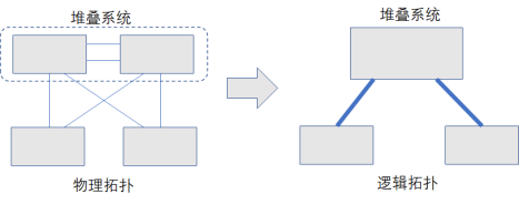
▷Simplified Networking▷
In a stacking system, switches provide redundancy for each other and can also achieve cross-device link redundancy. When the uplink of one device in the stacking system fails, traffic from that device can be forwarded through the stacking link.
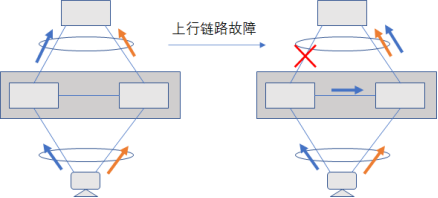
▷Increased Reliability▷
When the uplink bandwidth of a switch is insufficient, a new switch can be added to form a stacking system with the original switch, configuring multiple physical links of the switch into a link group, thereby increasing the uplink bandwidth of the switch.
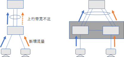
▷Expanded Bandwidth▷
While the application of stacking brings the above benefits, its limitations are becoming increasingly apparent with technological advancements, which is determined by the nature of stacking. The member switches of a stacking system have tightly coupled management, control, and forwarding planes, leading to the following issues:
-
Single Control Plane: The master switch in the stacking system controls the entire stacking system. If the stacking system splits, it will cause business interruption.
-
Complex Upgrades: Due to the tight coupling among member switches in a stacking system, only two devices can be upgraded together. A failed upgrade will cause all business networks in the stacking system to be interrupted. Even though Huawei switches have a fast upgrade method to minimize business interruptions during the upgrade process, there still remains a risk of business interruption.
In data center rooms, the stacking technology applied to different devices varies slightly, broadly categorized into two types: the iStack for box switches and the CSS for chassis switches.
The Cluster Switch System (CSS) is the stacking of chassis switches, which only supports two switches forming a stacking system. How are chassis switches stacked? What is the connection method? What is the working principle? Before this, it is necessary to have a certain understanding of the architecture of chassis switches. Taking CE12804 as an example, the composition modules are divided into:
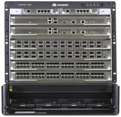
CE12804
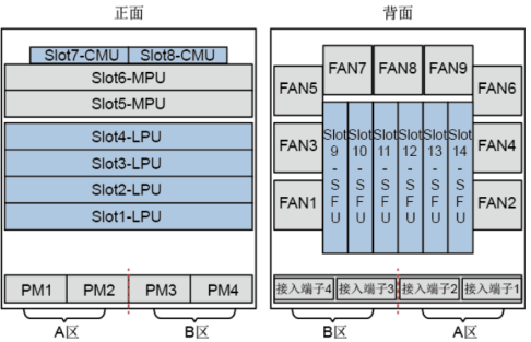
▷CE12804 Chassis Slot Distribution Diagram▷
-
MPU: Main Processing Unit, responsible for the control and management of the system.
-
SFU: Switch Fabric Unit, responsible for data plane data line-speed switching.
-
CMU: Centralized Monitoring Unit, mainly provides monitoring, management, and energy-saving features.
-
LPU: Line Processing Unit, interface board.
-
PM: Power Module.
-
FAN: Fan Module.
Having understood the composition modules of the switches, let’s look at how stacking systems are connected. In CSS, the connecting links are divided into two types based on their functions: management links and forwarding links. Management links are responsible for the forwarding of stacking system management and maintenance messages; forwarding links are responsible for the forwarding of business data messages across devices in the stacking system. Based on the different connection methods of management links, stacking connection methods are divided into: direct connection of the main control board and direct connection of the service board.
-
Main Control Board Direct Connection: Management links and forwarding links are separated. The management link connects through the SIP port of the main control board (MPU), which is dedicated to connecting stacking management links and consists of a GE electrical interface and a GE optical interface. Each main control board has two SIP ports, while the forwarding link connects through the ports of the service board (LPU).
-
Service Board Direct Connection: Management links and forwarding links are combined, connecting both through the ports of the service board (LPU).
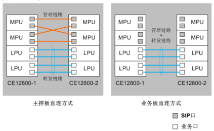
▷Stacking Connection Method Diagram▷
The management links and forwarding links of the main control board direct connection are deployed separately and do not affect each other, providing high overall reliability, and the main control board direct connection method is recommended. Having understood the stacking connection methods, let’s learn some basic concepts in stacking.
-
The member switches in the stacking system are referred to as member switches, which can be divided into the following roles based on functionality:
The master switch (Master) is responsible for managing the entire stack. There is only one master switch in the stack.
-
Stack Domain: Switches connected through stacking links form a stack, and the collection of these member switches is a stack domain. To accommodate various networking applications, multiple stacks can be deployed within the same network, distinguished by domain numbers (DomainID).
-
Stack Member ID: The numbering of stacking member switches (Member ID), used to identify and manage member switches. The stacking member IDs of all member switches in the stack are unique.
-
Stack Priority: Mainly used to determine the roles of member switches during the role election process; the higher the priority value, the higher the priority, and the greater the likelihood of being elected as the master switch.
-
Stack Port: A dedicated logical port for stacking, which needs to be bound to physical stacking ports. A stack port can bind multiple physical member ports to enhance stacking reliability and bandwidth. Each device supports one stack port; when stacking functionality is not enabled, it is Stack-Port1; when enabled, it is Stack-Portn/1, where n is the stacking member ID of the device.
-
Stack Physical Member Port: The physical ports configured for stacking mode, used for connections between stacking member switches.
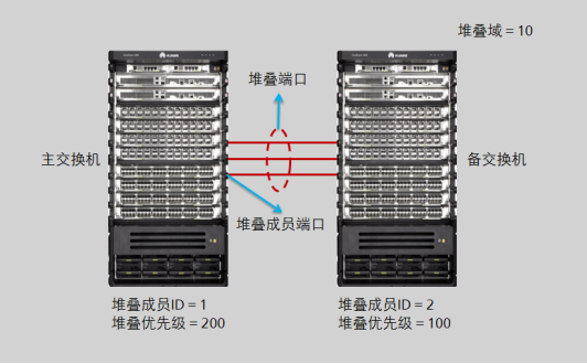
▷CSS Basic Concept Diagram▷
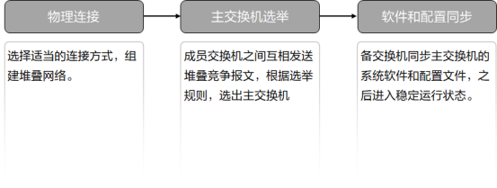
▷Stacking Construction Process▷
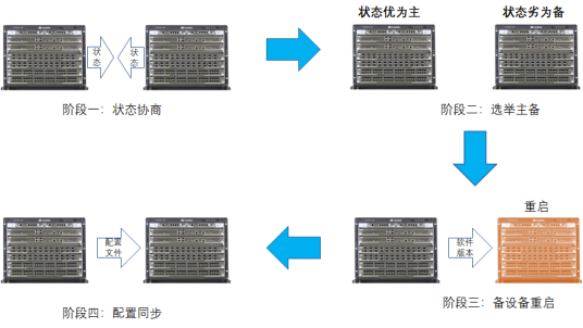
▷Stacking Construction Process▷
Two switches are connected with stacking cables, and after configuring the relevant stacking settings, the stacking system can be established.
Master Switch Election
When establishing a stack, member switches exchange stacking competition messages. The master switch is selected to manage the entire stacking system; the other becomes the standby switch, acting as a backup for the master switch. The election rules for the master switch are as follows (judging from the first rule downwards until the optimal switch is found):
1. Running state comparison, the switch that starts up first is the master switch.–Better
2. Stack priority comparison, the switch with a higher priority is the master switch.–Higher
3. Software version comparison, the switch with the newer software version is the master switch.–Newer
4. Main control board quantity comparison, the switch with more main control boards is the master switch.–More
5. Bridge MAC address comparison, the switch with the smaller MAC address is the master switch.–Smaller
After stacking is established, the main control board of the master switch becomes the primary main control board of the stacking system, serving as the main management role for the entire system. The main control board of the standby switch becomes the backup main control board of the stacking system, serving as the backup management role.
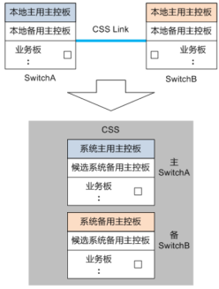
Software Version and Configuration Synchronization
The software versions of the two switches when forming a stack do not need to be the same, as long as the versions are compatible. Once the master switch is selected, if the software versions of the master and standby switches differ, the standby switch will download the new software version from the master switch and restart using the new software version to join the stack.
The stack has a strict configuration file synchronization mechanism to ensure that multiple switches in the stack can operate as a single device in the network.
-
When establishing the stack, member switches use their respective configuration files during the startup phase. After startup, the standby switch merges its stacking-related configurations into the configuration file of the master switch, forming the configuration file of the stacking system.
-
After the stack is operating normally, the master switch, as the management node of the stacking system, is responsible for synchronizing user configurations to the standby switch, ensuring that the configurations of each member switch in the stack remain consistent at all times.
Through immediate synchronization, all member switches in the stack maintain the same configuration. Even if the master switch fails, the standby switch can still perform functions according to the same configuration.
The stacking system presents itself as a single virtual device, communicating with other devices using a unique IP address and MAC address. Once the stack is established, member switches exist as a single virtual device in the network, with the master switch managing the entire stacking system. We can log into the stacking system through any member device to manage the entire stacking system. Regardless of the method used, logging into the stacking system from any member switch effectively logs into the master switch.
Ways to Log into the Stacking System:
-
Local Login: Log in through the Console port of any member device.
-
Remote Login: Log in remotely through the management port or other Layer 3 interfaces of any member device using Telnet, STelnet, etc.
The Eth-Trunk interface selects the outgoing interface through a HASH algorithm. Traffic entering the stack may be forwarded across devices, but due to the limited bandwidth of the stacking line, cross-device traffic forwarding increases the bandwidth burden on the stacking line and reduces forwarding efficiency. This issue can be resolved by enabling the local forwarding feature of the stacking device, where traffic entering from the device is prioritized to be forwarded out from that device’s outgoing interface; if the outgoing interface of that device fails, traffic is forwarded out through the interfaces of other member switches.
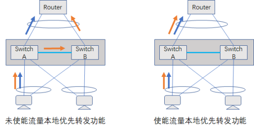
▷Local Priority Forwarding Diagram▷
As shown, when the local priority forwarding feature is not enabled on the stacking device, some traffic will be forwarded through the stacking line from SwitchB. After enabling local priority forwarding, traffic entering from SwitchA will be prioritized to be forwarded from SwitchA’s outgoing interface.
Configuration Command:
[~SwitchB] interface eth-trunk 1
[~SwitchB-Eth-Trunk1] undo local-preference disable
#Enable Eth-Trunk interface local priority forwarding on the stacking device
After the stacking system is established, the master and standby switches periodically send heartbeat messages through the stacking cable to maintain the stack. Faults are unavoidable; once the stacking cable or main control board fails, or the switches restart, the stacking system may split into two independent switches. As shown:
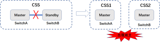
▷Dual-Master Fault▷
After the split, the two switches do not know each other’s status. The original master switch retains its role, while the original standby switch becomes the master switch, resulting in a “dual-master” situation. These two switches exhibit the same information in the entire network, communicating with external devices using the same IP and MAC addresses, leading to IP and MAC address conflicts, causing network faults. Therefore, we need to avoid the occurrence of dual masters—this is the dual-master detection technology.
Dual-Master Detection (DAD) is a protocol for detecting and handling stack splits. After configuring dual-master detection, the master switch sends DAD competition messages on the detection link. After a stack split, the split portions of the stacking system exchange competition messages and compare the received competition message information with their own competition information. If the local competition prevails, no action is taken, and the state remains active (normal working state), forwarding business messages normally; if the local competition fails, all business ports except the reserved port are set to Error-Down, entering Recovery state (business disabled state), ceasing to forward business messages.
The competition rules for DAD detection are as follows (judging from the first rule downwards until the optimal switch is found):
1. (Only applicable to the main control board direct connection method) Comparison of the Error-Down state of all business ports on the switch; the switch with no Error-Down ports has higher priority:
-
Due to no forwarding link causing Error-Down (no-stack-link).
-
Due to link failures between the interface board and the switching fabric board causing Error-Down (fabric-link-failure). When both Error-Down conditions exist, the switch with the no-stack-link Error-Down has higher priority.
2. Stack priority comparison; the switch with a higher stack priority has higher competition priority.
3. Device MAC address comparison; the switch with the smaller MAC address has higher competition priority.
DAD detection methods include the following:
Business Port Direct Connection Detection Method
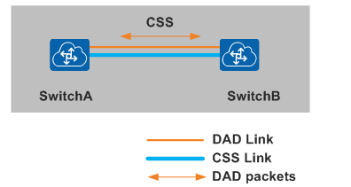
Features: The dual-master detection between stacking member switches is conducted through dedicated links connected via business ports; in the business port direct connection detection method, the DAD messages use BPDU messages, so the direct connection detection link can also connect through intermediate devices.
Configuration
interface 10ge1/0/5
dual-active detect mode direct
interface 10ge2/0/5
dual-active detect mode direct
Advantages and Disadvantages: Requires exclusive use of 10GE business ports, but detection speed is the fastest among Eth-Trunk port proxy detection methods.
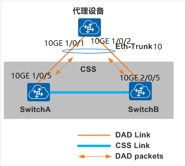
Features: Dual-master detection across devices connected via Eth-Trunk links;
Configuration:
Stacking System
interface eth-trunk10
trunkport 10ge 1/0/5 #For chassis switches, the ports are 10ge 1/1/0/5 and 10ge 2/1/0/5
trunkport 10ge 2/0/5
dual-active detect mode relay
Proxy Device
interface eth-trunk10
trunkport 10ge 1/0/1
trunkport 10ge 1/0/2
dual-active proxy
Advantages and Disadvantages: No need to occupy additional interfaces; Eth-Trunk interfaces can run DAD proxy detection and other services simultaneously. Requires proxy devices that support DAD proxy functionality (currently supported by the CloudEngine series switches; S system switches support this from version v200R003C00 onwards).
Management Port Detection Method
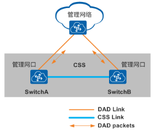
Features: Dual-master detection conducted through the management port links of stacking member switches; the management port must be configured with an IP address, and after stacking, the entire system only displays one management port MEth0/0/0, where only this management port needs to be configured with an IP address.
Configuration:
interface meth 0/0/0/0
ip address 192.168.10.10 24
dual-active detect enable
Advantages and Disadvantages: The simplest implementation, requiring no additional interfaces or proxy devices.
Stack Port Detection Method (Only for CSS)
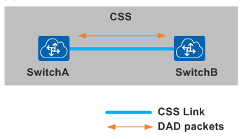
Features: Dual-master detection conducted through the links between stack physical member ports.
Configuration:
interface stack-port 1/1
dual-active detect mode direct
interface stack-port 2/1
dual-active detect mode direct
Advantages and Disadvantages: Only applicable when using chassis switches and the connection method is main control board direct connection.
DAD Fault Recovery Mechanism
After the stacking link fault is repaired, the split stacking system merges again. The switches in Recovery state will restart, and the Error-Down business ports will return to normal, restoring the entire stacking system.
(To be continued)
Battle Report | 88 People Passed HCIE in May at Taike Education!!!
Taizhang Knowledge | In-Depth Understanding of Java Reflection
Industry-Education Integration for Mutual Development | 2023 Industry-Education Integration New Generation Information Technology Talent Cultivation Seminar Successfully Held
2023 Huawei ICT Academy Teacher and Student Discount Exam Voucher Application Instructions and Operation Guidelines