This article is reprinted from the Jishu Community
Jishu Column: Shanghai Hangxin
With the continuous development of the automotive industry, the number of automotive electronic control units has gradually increased, and the signal exchange between various control units has become more complex. The CAN bus connects the various electronic control units within the vehicle into a local area network, enabling information sharing and greatly optimizing the vehicle’s wiring.
Next, we will continue to share knowledge related to CAN technology.
CAN Layered Architecture
It consists of three layers: the application layer, the data link layer, and the physical layer.
• Application Layer: This layer interacts with the operating system or application programs of CAN devices.
• Data Link Layer: It connects the actual data to the protocol in terms of sending, receiving, and verifying data.
• Physical Layer: It represents the actual hardware, namely the CAN controller and transceiver.
Characteristics of the CAN Physical Layer
The CAN physical layer is divided into three parts: physical encoding implemented in the CAN controller chip, the physical media attachment that specifies the characteristics of the transceiver, and the physical media-dependent sublayer, which is specific to applications and not standardized.
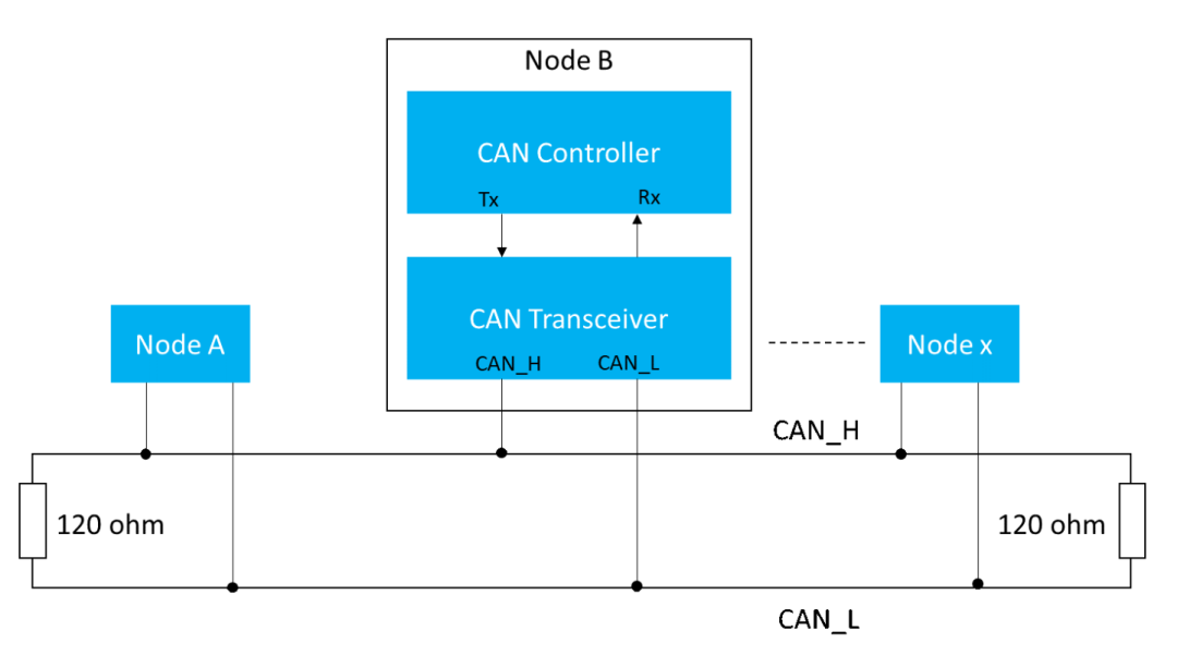
Figure 1. CAN Bus Wiring Diagram
Physical Coding Sublayer
The PCS includes bit encoding and decoding, and bit timing. It provides a connection unit interface for the transceiver chip and includes Tx and Rx pins, with bit-level errors also handled through bit stuffing.
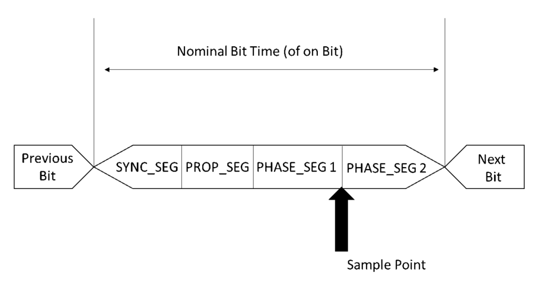
Bit Timing
For timing purposes, each bit on the CAN bus is divided into at least four time segments, logically divided into four segments:
-
-
-
-
One time quantum length, used for multiple units connected on the bus, achieving timing adjustment through this segment. When the bus voltage level changes (from dominant to recessive or recessive to dominant), it is expected that a bit edge will appear in this segment.
Used to compensate for the physical delays between nodes on the network, including the output delay of the sending unit, the propagation delay of the signal on the bus, and the input delay of the receiving unit.
The phase buffer segment is used to compensate for oscillator errors between nodes, further divided into Phase Buffer Segment 1 (PS1) and Phase Buffer Segment 2 (PS2), where the bus state is sampled at the end of this time segment. The two phase buffer segments PS1 and PS2 are used to compensate for edge phase errors on the bus.
The sampling point is a time point within the bit time, at which the bus level is read and analyzed. The sampling point within the bit time determines whether the CAN bus voltage is recessive or dominant. It is expressed as a percentage of the bit time, with the position calculated from the start of the bit time, located between phase 1 and phase 2.
Handling Bit-Level Errors
The CAN protocol follows NRZ encoding for transmission. The logical level does not change between bit intervals. CAN requires a change in logical level for resynchronization. Therefore, after five consecutive bits of the same logical level, one bit of the opposite logical level will be sent. This is known as bit stuffing, and the receiver can recognize it.
A node sending a bit always monitors the bus; if the bit sent by the transmitter differs from the bit value on the bus, an error frame is generated.
Physical Media Dependent Sublayer
This layer is implemented in the CAN transceiver chip, obtaining input from the CAN controller through Tx and Rx pins, driving the CANH and CANL lines. The transceiver is responsible for different bit rates, with the CAN bus speed referring to the CAN bus communication rate. The maximum CAN bus communication speed is 1 Mbit/sec. For specific applications, some CAN controllers will handle higher speeds, exceeding 1 Mbit/sec. The low-speed CAN communication rate is 125 kbits/sec.
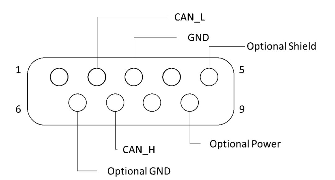
The media-dependent sublayer is highly application-specific, with the pin assignments of different connectors standardized belonging to this layer. Various connectors include DB9, OBD II.
The CAN bus is typically accessed via connectors.
Figure 3. CAN Bus DB9 Pin Assignment
CAN Bus Support in Various Microcontrollers
Microcontrollers should have CAN hardware and software, providing CAN drivers for communication. The Python-CAN library can also be used to provide abstract drivers for the hardware components of microcontrollers and to send and receive messages over the CAN network. The Python CAN bus is also used for testing hardware and CAN bus data logging.
CAN Bus Shield for Arduino
• The CANbus Shield provides CAN bus capabilities for Arduino with a CAN controller featuring SPI interface and CAN transceiver.
• Arduino with CAN bus helps retrieve information such as vehicle speed, fuel consumption, temperature, etc., from the ECU.
• The Arduino CAN library is used to send and receive CAN messages over the CAN bus.
The Raspberry Pi does not have specific hardware, namely a CAN controller and CAN transceiver, to support the CAN protocol. The Raspberry Pi software does not support the CAN bus, but the Raspberry Pi supports CAN communication via SPI interface.
The Raspberry Pi connects to an external CAN controller supported by the board via the SPI interface, with the CAN controller connected to the CAN transceiver through the Rx and Tx lines.
Examples of CAN Controllers: SJA100, MCP2515
Examples of CAN Transceivers: TJA1040, MCP2551
The ACM32-F0/F4 chips have 1 to 2 built-in CAN controllers and provide corresponding CAN bus interface driver libraries, paired with external CAN transceivers to ensure safe and reliable CAN bus data communication.
How to Read CAN Bus Data?
When the CAN bus is connected to external tools such as the Microchip CAN Bus Analyzer or CAN Bus Wire Shark, CAN bus data can be accessed via a CAN USB adapter, which provides instant connection to the USB port of a computer or PC. The CAN USB adapter can also be controlled from anywhere via Ethernet, internet, or intranet. CAN Bus Wireshark is a tool for Linux systems, especially known for Ethernet network analysis; it displays CAN messages using SocketCAN, a set of drivers and network stack, hence referred to as Linux CAN bus. CAN to USB helps external tools obtain messages from the CAN network, which are then used for monitoring and debugging tools to receive or transmit information.
However, these messages are in raw format. Thus, the data collected from these data loggers is converted to scaled engineering values using a CAN bus decoder. The data collected from data loggers can also be stored on an SD card, which helps control vehicle settings for improved efficiency. The collected CAN bus data can be used for fleet management, R&D, diagnostics, etc.
Testing the CAN Bus with a Multimeter
Testing is necessary to check for any CAN bus faults that may occur, such as wiring, ECU, or voltage supply faults in any component of the CAN network. Troubleshooting the CAN bus, such as adding a 120-ohm termination resistor at the physical end of the CAN bus line, can diagnose problems. By testing with a multimeter, ensure that the termination resistor is 120 ohms and that the resistance is appropriate and not broken. You can also test the transmitted data by switching the multimeter to AC voltage.
How to Determine if a Vehicle has a CAN Bus?
Vehicles equipped with a CAN bus contain CAN bus LEDs and CAN-BUS HID kits. The CAN bus LED communicates with the vehicle’s advanced systems; when this LED is off, the vehicle emits a warning. The CAN BUS HID KIT acts as a DC to AC converter and helps turn on the lights initially using high-voltage current. Once the lights are on, they require a lower voltage current. However, when HID uses low power, the CAN bus system assumes the light bulb is off and issues a warning. To avoid this, a HID conversion kit is used, which communicates with the CAN bus system to indicate that there is a working light bulb. These warnings inform us that the vehicle is equipped with a CAN bus.
CAN bus hacking poses a threat to consumers. CAN bus vehicles have adopted many wireless technologies, such as Bluetooth, for answering calls or playing music. When the in-car system connects to the CAN bus inside the vehicle and has Wi-Fi connectivity, hackers can easily gain access to the CAN bus and control the vehicle. Wi-Fi hotspots are popular in cars, making it possible for someone who knows the car’s IP address to track the vehicle. This has led car manufacturers to protect the data transmitted over the CAN bus network.
Reprinted from | Jishu Community
Copyright belongs to the original author. If there is any infringement, please contact for deletion.
END


关于安芯教育


安芯教育是聚焦AIoT(人工智能+物联网)的创新教育平台,提供从中小学到高等院校的贯通式AIoT教育解决方案。
安芯教育依托Arm技术,开发了ASC(Arm智能互联)课程及人才培养体系。已广泛应用于高等院校产学研合作及中小学STEM教育,致力于为学校和企业培养适应时代需求的智能互联领域人才。