Introduction
This article covers the following topics:
-
What is the difference between Single-Ended Input and Differential Input?
-
What are Fully Differential, True Differential, and Floating Differential?
-
What are Reference Voltage (Vref) and Common Mode Voltage (Vcm)?
Single-Ended Input
The simplest connection between a sensor and an ADC is the Single-Ended Input. In this connection, the sensor and the ADC share the same ground, and a varying analog signal is provided on the single-ended input.
Inside the Arduino MCU, there is such an ADC:
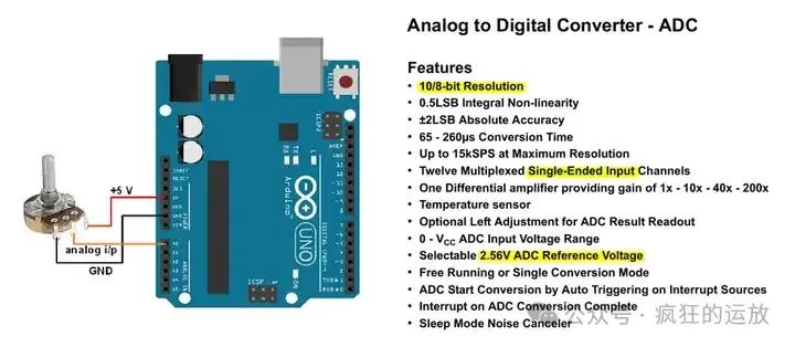
The highlighted points in the figure are: 10/8-bit Resolution, Single-Ended Input, and 2.56V ADC Reference Voltage.
To interpret this collectively:
-
The resolution of the ADC is n, and the results of the ADC conversion are integers between 0 and 2^n – 1;
-
If n = 10, the maximum value 1023 corresponds to the reference voltage; the minimum value 0 corresponds to ground;
-
The reference voltage (Vref) defines the range of the ADC (or dynamic range), which defaults to 2.56V but can be configured;
-
When the input signal ≥ reference voltage, the output conversion result is the maximum, which is the value 1023;
-
When the input signal ≤ ground, the output conversion result is the minimum, which is the value 0;
-
When the input signal is between ground and reference voltage, the output is a proportionate conversion result;
For example, when the input signal is 1.25V, the output value = 1.25 / 2.56 * 1024 = 500.
Differential Input 1: Fully Differential Input
Some sensors and communication devices use a pair of cables to represent signals. When connecting to the ADC, one is the “positive input” and the other is the “negative input.” The differential signal is the voltage difference between these two inputs. This method helps suppress common mode noise interference.
The differential signal has polarity; when the positive input is greater than the negative input, the differential signal is positive; otherwise, it is negative. A negative differential signal does not indicate that the input is negative voltage; it simply means that the “negative input” is greater than the “positive input.”
TI provides a differential ADC as follows:
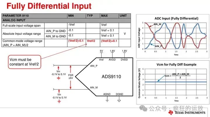
Like Single-Ended Input, the reference voltage (Vref) determines the range. However, the differential ADC has a range of 2 times Vref because both inputs can vary between [0, Vref]; when the positive input is 0 and the negative input is Vref, the differential signal is -Vref; when the positive input is Vref and the negative input is 0, the differential signal is Vref. Therefore, the range is [-Vref, Vref], which is twice that of Single-Ended Input. Accordingly, the conversion result of the differential ADC is [-2^(n-1), 2^(n-1)-1], covering twice the Vref.
Unlike Single-Ended Input, the differential ADC has another parameter – Common-Mode Voltage (Vcm). This parameter refers to the average level of the two inputs, generally positioned between the power supply and ground, as this is when the transistors at the input have the best linear characteristics.
Differential Input 2: True Differential Input
The above Fully Differential Input refers to the symmetry of the signals at the two inputs, which are 180° out-of-phase around Vcm.
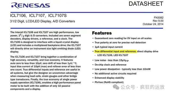
For True Differential Input, this requirement does not have to exist; its “positive input” is one signal, while the “negative input” can be a completely different signal.
The multimeter chip ICL7106 is such an ADC, as shown below, which appears in many low-cost multimeters:
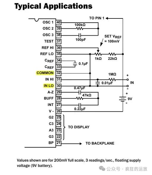
In the figure, IN HO and IN LO are the two inputs of the differential signal, while IN LO is connected to the COMMON pin, which applies a specific level to IN LO.
My personal understanding is that when the signal measurement system requires a large “DC bias voltage,” the “DC voltage bias” can be connected to one input (like IN LO) through True Differential Input, making the differential result match the range of the reference voltage. If Single-Ended Input were to be used to achieve this, a larger reference voltage would be needed to cover both the DC bias voltage and the actual signal, and a larger reference voltage is not conducive to conversion accuracy.
Below is a comparison provided by TI of Single-Ended and Differential ADC:
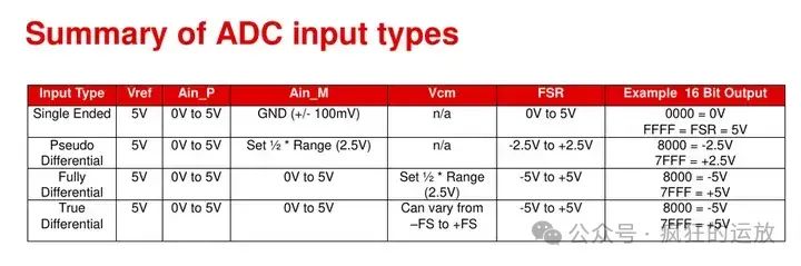
The figure also describes a Pseudo Differential type, which is simpler than True Differential because IN LO (shown as Ain_M in the figure) can only be a fixed level.
Differential Input 3: Floating Differential Input
The above differential inputs share the same ground with the ADC, but in some scenarios, different grounds may be encountered, referred to as Floating Differential Input:
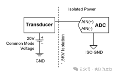
This situation arises when the signal has an independent power supply system, requiring electrical isolation (Galvanic isolation) to ensure that the common mode voltage of the differential input does not exceed the range that the ADC can withstand.
We can delve deeper into this topic later, but for now, consider: Are the signals measured by a multimeter Floating? Are the signals measured by an oscilloscope Floating? Are human physiological signals (such as ECG measurements) Floating?
Conclusion
Today we introduced several types of ADC inputs, such as Single-Ended, Fully Differential, True Differential, and Floating Differential. Understanding these requires grasping the two parameters: “Reference Voltage (Vref)” and “Common Mode Voltage (Vcm).”
References
References can be found online by searching for the keywords:
-
Arduino ATmega16U4/ATmega32U4 datasheet
-
TI SAR ADC input types: https://www.ti.com/video/6279972316001001
-
Renesas ICL7106 datasheet
-
Maxim / ADI Application Note 1108
This public account is designed for makers, providing interesting and useful hardware and software columns. Welcome to follow, like, and star~