Everyone is likely familiar with sensors, which are detection devices that can sense the information being measured and convert that information into electrical signals or other required forms of output according to certain rules, in order to meet the requirements for information transmission, processing, storage, display, recording, and control. Below, I will provide a brief overview of the common types of output signals from sensors and signal conditioning.
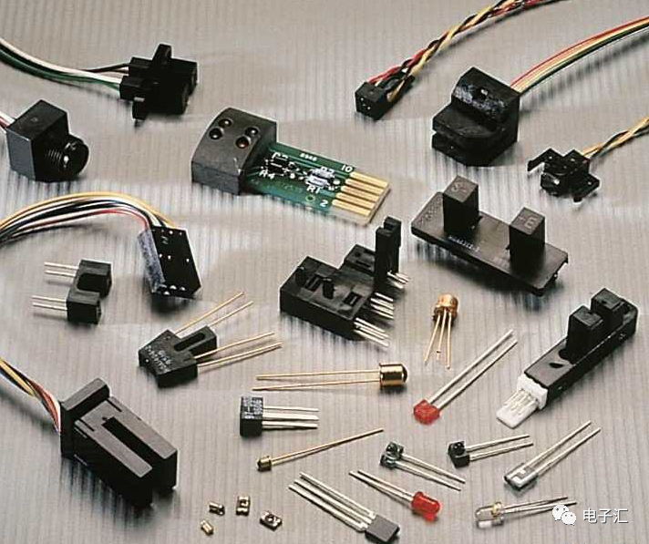
1. Common Types of Sensor Output Signals
The commonly used output signals can be divided into three types: incremental code signals, absolute code signals, and switch signals. Each of these has its own advantages and disadvantages.
Incremental Code Signals: These refer to signals where the change in the measured value is proportional to the number of cycles of the sensor output signal, meaning the magnitude of the output value is determined by the increment of the number of cycles of signal change. Generally, sensors such as grating displacement sensors, magnetic grating displacement sensors, and laser displacement sensors use methods like interference to measure displacement, and the output signal from these sensors is an incremental code signal.
Absolute Code Signals: These are signals that correspond to the state of the measured object. For example, in a code disk, each angular position corresponds to a set of codes, which are referred to as absolute codes. Absolute code signals have strong anti-interference capabilities; regardless of what happens during the measurement process, a certain state always corresponds to a specific set of codes after interference.
Switch Signals: Switch signals have only two states, 0 and 1, and can be seen as a special case of absolute codes with only one bit of coding. For example, the output of sensors such as limit switches and photoelectric switches is a switch signal.
2. Signal Conditioning for Sensors
Sensor elements (sensors) convert useful physical signals into electrical signals, such as: a piezoresistive bridge for measuring pressure, a piezoelectric sensor for detecting ultrasound, and an electrochemical cell for measuring gas concentration. The electrical signals generated by sensor elements are typically very small and in a non-ideal state, such as temperature drift and nonlinear transfer functions.
The sensor’s analog front end and sensor signal conditioners are used to amplify these small signals generated by the sensor elements to usable levels. The sensor includes a complete signal conditioning circuit, as well as circuits that can stimulate the sensor elements, manage power, and connect to external controllers.
To achieve signal conditioning or higher-level monitoring, it is often necessary to measure the outputs of multiple sensor elements. For example, processing the output of a typical piezoresistive bridge requires simultaneously measuring the outputs of the piezoresistive bridge and a temperature sensor. Additionally, processing the output of a thermocouple requires simultaneously measuring the output of the thermocouple and the sensor output to measure the temperature at the junction. Measuring the junction temperature is necessary to complete cold junction compensation. The situation where the same signal conditioner processes multiple sensing elements is referred to as a “multi-modal signal conditioner.”
Another aspect of sensor signal conditioning is the domain in which the signal conditioning occurs. The signal conditioning of the sensor’s resistive bridge element occurs in the analog domain. In sensors, signal conditioning occurs simultaneously in both the analog and digital domains. The latter case is referred to as “mixed-signal conditioning.”
A key component of mixed-signal conditioners is the analog-to-digital converter (ADC). Before the signal reaches the intelligent compensation module, the two sensor elements always have independent signal paths. After that, the module combines these two signals to produce a processed output.