1. Introduction
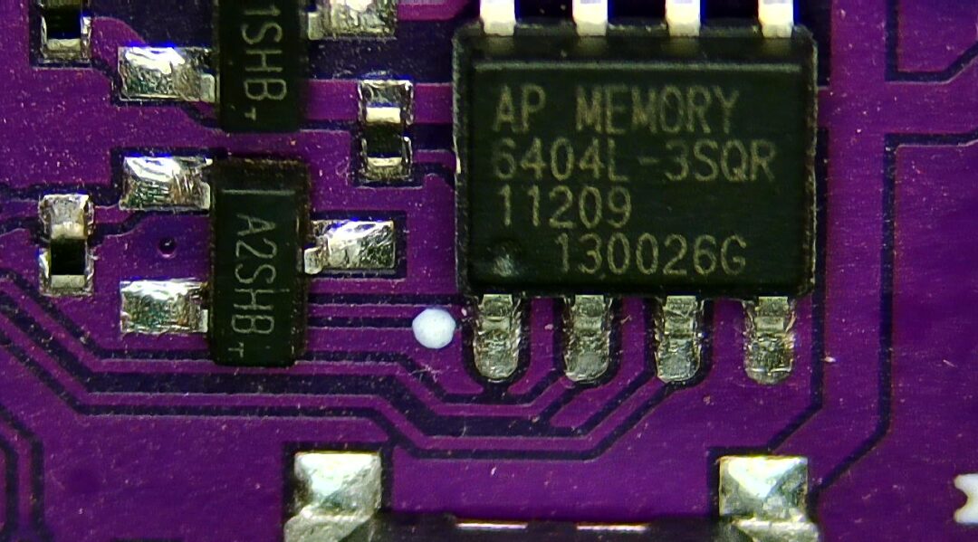
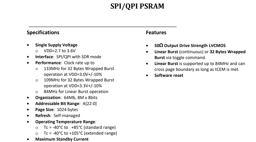
This small electronic badge contains many unique components. This AP Memory is a SPI interface SRAM with a capacity of 8MB. Below is a preliminary test of it.
2. Creating the Test Circuit
This RAM with SPI interface operates with a current from 2.7V to 3.6V. Its package seems to be universal, similar to another SPI interface RAM I tested in 2020, model 24LC1024. Below, we will build a test circuit using the same package.
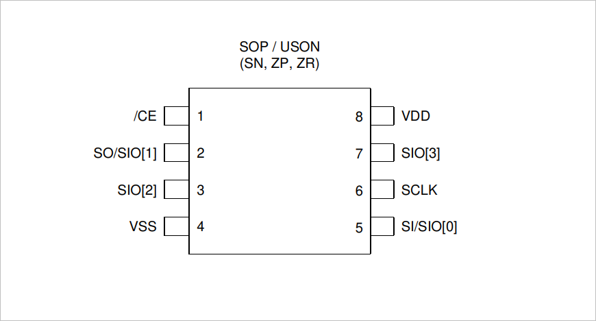
▲ Figure 1.2.1 APMemory PackageUsing the STM32F103 as the test controller, its six IOs connect to the SRAM for read/write operations. A rapid prototyping method is used to create the test circuit. After one minute, the test circuit board is obtained. Components are soldered, including a jumper completed with a 0-ohm resistor. Next, we will test it.
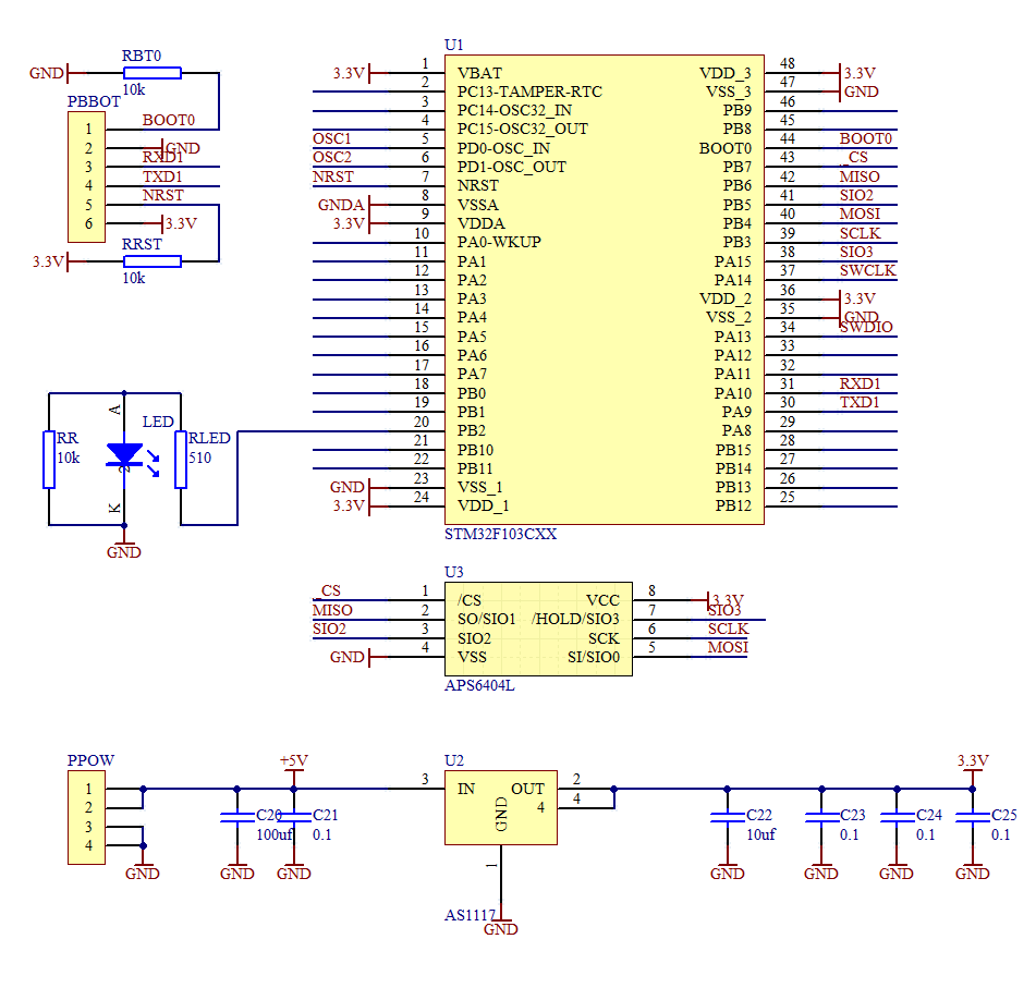
▲ Figure 1.2.2 Test Circuit Schematic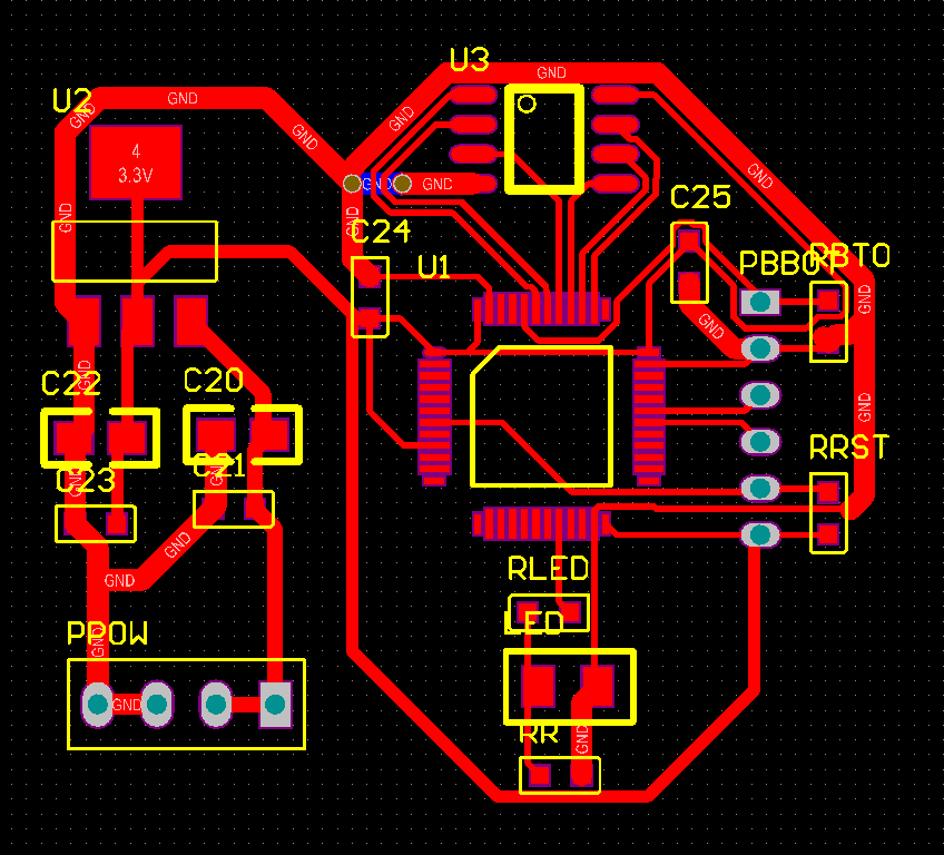
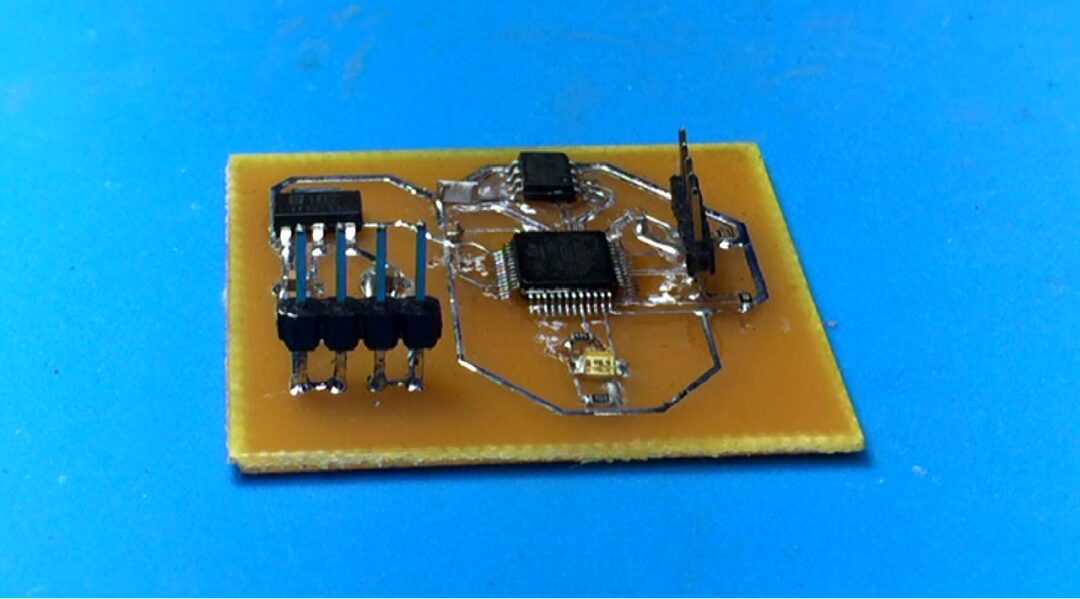
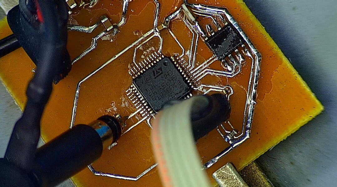
▲ Figure 1.2.3 Test Circuit PCBAD\Test\2023\TestAPM.PcbDoc
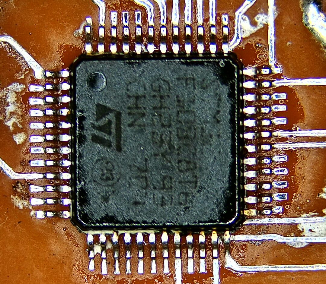
▲ Figure 1.2.4 Soldering the Chip with Solder Paste, Very Perfect3. Test Results
After soldering the circuit board, the APS6404L is tested. The basic read/write functions of the APS6404 are tested, followed by testing its capacity and read/write speed. Based on the APS6404 data sheet, the most basic slow SPI read/write process is written, simulating the SPI sequence using ordinary IO ports for easier portability. The program is downloaded. The basic read/write functions are normal.
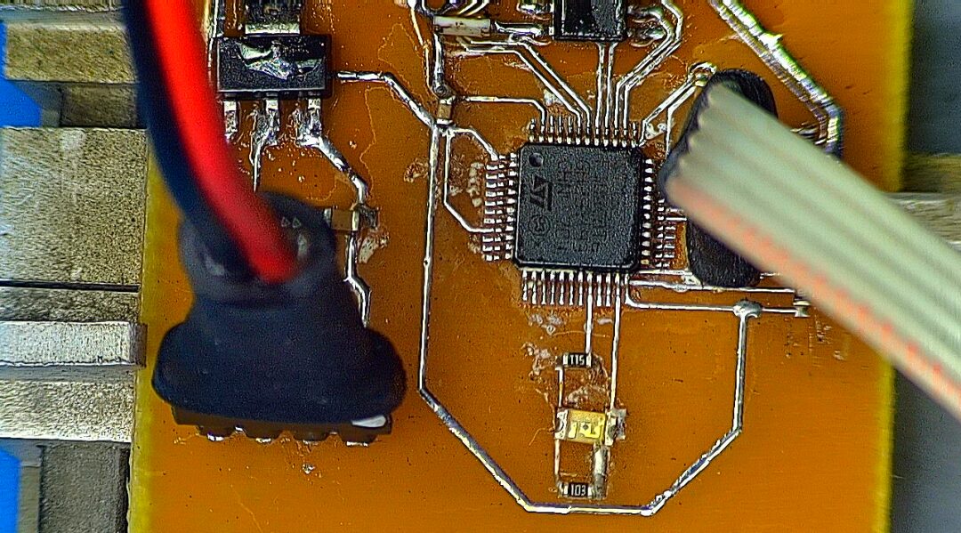
▲ Figure 1.3.1 Test Circuit BoardNext, we test the speed of the simulated SPI read/write of the serial RAM. Using the LED output port to indicate the start time of the RAM read/write, 0x800 zeros are filled into the APS6404L. By measuring the voltage signal at the LED port during read/write operations, the time used can be calculated. Then, dividing by 0x800 gives the average time for accessing a single byte of RAM. The measured access time is 4.62ms, and the access time for a single byte is 2.25 microseconds.
▲ Figure 1.3.2 Read/Write TimeSince a simulated SPI interface is used, the time required to access a single byte is relatively long. If the entire 8 megabytes are read through, it will take 19 seconds. Later, the reading speed can be improved through the microcontroller’s SPI hardware, or by accessing multiple IOs simultaneously to enhance read/write speeds.
※ Conclusion ※
This article documents the testing of the SPI interface serial SRAM, model APS6404L. The basic read/write functions have been tested, providing experience for future applications. The read/write speed has not yet reached its maximum interface speed.
References
APS6404L-3SQR QSPI PSRAM: https://www.apmemory.com/wp-content/uploads/APM_PSRAM_QSPI-APS6404L-3SQR-v2.3-PKG.pdf
[2]Microcontroller External RAM, Serial: https://blog.csdn.net/zhuoqingjoking97298/article/details/105891541
[3]23A1024/23LC1024: https://ww1.microchip.com/downloads/en/DeviceDoc/20005142C.pdf