The Arm processor is designed based on the principles of Reduced Instruction Set Computing (RISC). The instruction set and associated decoding mechanisms are relatively simple, featuring a 32-bit Arm instruction set and a 16-bit Thumb instruction set. The Arm instruction set is efficient but has low code density, while the Thumb instruction set offers better code density while maintaining most performance advantages of Arm. It is a subset of the Arm instruction set. All Arm instructions can be conditionally executed, whereas only one Thumb instruction has conditional execution capability. Arm programs and Thumb programs can call each other, and the overhead of switching states between them is almost zero.
The Cortex-M0 processor is based on the ARMv6-M architecture and is a processor with balanced power consumption and performance. The Cortex-M0 supports a small instruction set of only 56 instructions, most of which are 16-bit instructions.
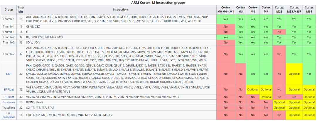
Comparison of Arm Cortex-M instruction sets:
1. Instruction Set
1.1 Moving Data Within the Processor
MOV  <Rd>, <Rm> ; Rm and Rn can be high or low registers.
MOVS <Rd>, <Rm>
MOVS <Rd>, #immed8 ; 8-bit immediate value

MRS  <Rd>, <SpecialReg>
MSR  <SpecialReg>, <Rd>
1.2 Memory Access
It is important to ensure that the accessed memory address is aligned. The ARMv6-M architecture (including Cortex-M0 and Cortex-M0 processors) does not support unaligned transfers. Any attempt for unaligned memory access will cause a HardFault exception.
LDR  <Rt>,[<Rn>, <Rm>]    ; Rt = memory[Rn + Rm]
STR  <Rt>,[<Rn>, <Rm>]    ; memory[Rn + Rm] = Rt
LDRH <Rt>,[<Rn>, <Rm>]    ; Rt = memory[Rn + Rm]
STRH <Rt>,[<Rn>, <Rm>]    ; memory[Rn + Rm] = Rt
LDRB <Rt>,[<Rn>, <Rm>]    ; Rt = memory[Rn + Rm]
STRB <Rt>,[<Rn>, <Rm>]    ; memory[Rn + Rm] = Rt

LDRSH <Rt>,[<Rn>, <Rm>]   ; Rt = SignExtend(memory[Rn + Rm])
LDRSB <Rt>,[<Rn>, <Rm>]   ; Rt = SignExtend(memory[Rn + Rm])

LDR  <Rt>,[<Rn>, #immed5] ; Rt = memory[Rn + ZeroExtend (#immed5<<2)]
STR  <Rt>,[<Rn>, #immed5] ; memory[Rn + ZeroExtend(#immed5<<2)] = Rt
LDRH <Rt>,[<Rn>, #immed5] ; Rt = memory[Rn + ZeroExtend (#immed5<<1)]
STRH <Rt>,[<Rn>, #immed5] ; memory[Rn + ZeroExtend(#immed5<<1)] = Rt
LDRB <Rt>,[<Rn>, #immed5] ; Rt = memory[Rn + ZeroExtend (#immed5)]
STRB <Rt>,[<Rn>, #immed5] ; memory[Rn + ZeroExtend(#immed5)] = Rt

LDR  <Rt>,[SP, #immed8]   ; Rt = memory[SP + ZeroExtend(#immed8<<2)]
STR  <Rt>,[SP, #immed8]   ; memory[SP + ZeroExtend(#immed8<<2)] = Rt

LDR  <Rt>,[PC, #immed8]   ; Rt = memory[WordAligned(PC+4)+ZeroExtend(#immed8<<2)]
LDR  <Rd>, =immed32       ; pseudo instruction translated to LDR <Rt>,[PC, #immed8]
LDR  <Rd>, label          ; pseudo instruction translated to LDR <Rt>,[PC, #immed8]

LDM <Rn>,{<Ra>,<Rb>,...} ; Load Multiple
// Ra = memory[Rn]
// Rb = memory[Rn + 4],
// ...

LDMIA <Rn>!, {<Ra>,<Rb>,...} ; Load Multiple Increment After
LDMFD <Rn>!, {<Ra>,<Rb>,...}
// Ra = memory[Rn],
// Rb = memory[Rn + 4],
// ...
// and then update Rn to last read address plus 4.

STMIA <Rn>!, {<Ra>,<Rb>,...} ; Store Multiple Increment After
STMEA <Rn>!, {<Ra>,<Rb>,...}
// memory[Rn] = Ra,
// memory[Rn + 4] = Rb,
// ...
// and then update Rn to last store address plus 4.
1.3 Stack Space Access
PUSH {<Ra>, <Rb>, ..}
PUSH {<Ra>, <Rb>, .., LR}
POP  {<Ra>, <Rb>, ..}
POP  {<Ra>, <Rb>, .., PC}
1.4 Arithmetic Operations
ADD  <Rd>, <Rm>          ; Rd = Rd + Rm. Rd, Rm can be high or low registers.

ADDS <Rd>, <Rn>, <Rm>    ; Rd = Rn + Rm
SUBS <Rd>, <Rn>, <Rm>    ; Rd = Rn – Rm
ADDS <Rd>, <Rn>, #immed3 ; Rd = Rn + ZeroExtend(#immed3)
SUBS <Rd>, <Rn>, #immed3 ; Rd = Rn – ZeroExtend(#immed3)
ADDS <Rd>, #immed8       ; Rd = Rd + ZeroExtend(#immed8)
SUBS <Rd>, #immed8       ; Rd = Rd – ZeroExtend(#immed8)

ADCS <Rd>, <Rd>, <Rm>    ; Rd = Rd + Rm + Carry
SBCS <Rd>, <Rd>, <Rm>    ; Rd = Rd – Rm – Borrow

ADD  SP, SP, #immed7     ; SP = SP + ZeroExtend(#immed7<<2)
SUB  SP, SP, #immed7     ; SP = SP – ZeroExtend(#immed7<<2)
ADD  SP, <Rm>            ; SP = SP + Rm. Rm can be high or low register.

ADD  <Rd>, SP, <Rd>      ; Rd = Rd + SP. Rd can be high or low register.
ADD  <Rd>, SP, #immed8   ; Rd = SP + ZeroExtend(#immed8<<2)

ADD  <Rd>, PC, #immed8   ; Rd = (PC[31:2]<<2) + ZeroExtend(#immed8<<2)
ADR  <Rd>, <label>       ; pseudo instruction translated to ADD <Rd>, PC, #immed8

RSBS <Rd>, <Rn>, #0       ; Rd = 0 – Rm, Reverse Subtract (negative)

MULS <Rd>, <Rm>, <Rd>    ; Rd = Rd * Rm

CMP <Rn>, #immed8        ; Rd – ZeroExtended(#immed8)
CMP <Rn>, <Rm>           ; Rn – Rm
CMN <Rn>, <Rm>           ; Rn – NEG(Rm)
1.5 Logical Operations
ANDS <Rd>, <Rd>, <Rm> ; Rd = AND(Rd, Rm)
ORRS <Rd>, <Rd>, <Rm> ; Rd = OR(Rd, Rm)
EORS <Rd>, <Rd>, <Rm> ; Rd = XOR(Rd, Rm)
BICS <Rd>, <Rd>, <Rm> ; Rd = AND(Rd, NOT(Rm))
MVNS <Rd>, <Rm>       ; Rd = NOT(Rm)
TST  <Rn>, <Rm>       ; AND(Rn, Rm)
1.6 Shift and Rotate Operations
ASRS <Rd>, <Rm>, #immed5 ; Rd = Rm>>immed5
LSLS <Rd>, <Rm>, #immed5 ; Rd = Rm<<#immed5
LSRS <Rd>, <Rm>, #immed5 ; Rd = Rm>>#immed5ASRS <Rd>, <Rd>, <Rm>    ; Rd = Rd>>Rm
LSLS <Rd>, <Rd>, <Rm>    ; Rd = Rd<<Rm
LSRS <Rd>, <Rd>, <Rm>    ; Rd = Rd>>RmRORS <Rd>, <Rd>, <Rm>    ; Rd = Rd rotate right by Rm bits
// Rotate_Left(Data, offset) = Rotate_Right(Data, (32-offset))
1.7 Unpacking and Byte-Reverse Operations
These reverse instructions are often used to convert data between little-endian and big-endian formats.
REV <Rd>, <Rm> ; Byte-Reverse Word
// Rd = {Rm[7:0], Rm[15:8], Rm[23:16], Rm[31:24]}

REV16 <Rd>, <Rm> ; Byte-Reverse Packed Half Word
// Rd = {Rm[23:16], Rm[31:24], Rm[7:0] , Rm[15:8]}

REVSH <Rd>, <Rm> ; Byte-Reverse Signed Half Word
// Rd = SignExtend({Rm[7:0] , Rm[15:8]})
1.8 Extension Operations
These are usually used for data type conversions.
SXTB <Rd>, <Rm> ; Signed Extended Byte
// Rd = SignExtend(Rm[7:0])

SXTH <Rd>, <Rm> ; Signed Extended Half Word
// Rd = SignExtend(Rm[15:0])

UXTB <Rd>, <Rm> ; Unsigned Extended Byte
// Rd = ZeroExtend(Rm[7:0])

UXTH <Rd>, <Rm> ; Unsigned Extended Half Word
// Rd = ZeroExtend(Rm[15:0])
1.9 Program Flow Control
B <label>       ; Branch, Branch range is ±2046 bytes of current PC
B<cond> <label> ; Conditional Branch, Branch range is ±254 bytes of current PC
BL <label>      ; Branch and Link, Branch range is ±16 MB of current PC
BX <Rm>         ; Branch and Exchange
BLX <Rm>        ; Branch and Link with Exchange
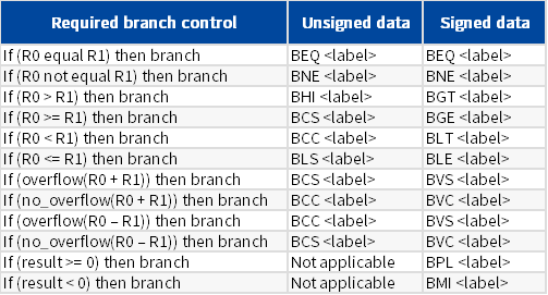
Conditional branch instruction B
1.10 Memory Barrier Instructions
Memory barrier instructions are supported on the Cortex-M0 and Cortex-M0 processors, providing better compatibility between Cortex-M processors and other ARM processor families.
// Data memory barrier, ensures that all memory accesses are completed before new memory accesses are submitted.
DMB
// Data synchronization barrier, ensures that all memory accesses are completed before executing the next instruction.
DSB
// Instruction synchronization barrier, flushes the pipeline and ensures that all previous instructions are completed before executing a new instruction.
ISB
1.11 Exception Related Instructions
SVC <immed8> ; Supervisor call
CPSIE I      ; Enable Interrupt (Clearing PRIMASK)
CPSID I      ; Disable Interrupt (Setting PRIMASK)
1.12 Sleep Mode Function Instructions
// Wait for interrupt, halt program execution until an interrupt arrives, if the processor enters debug state.
WFI
// Wait for event, clears internal event register if set and continues execution. Halts program execution until an event (such as an interrupt) arrives, if the processor enters debug state.
WFE
// Send event, sets local event register and sends an event pulse to other microprocessors in a multiprocessor system.
SEV
1.13 Other Instructions
NOP           ; No Operation
BKPT <immed8> ; Break point
YIELD         ; Execute as NOP on the Cortex-M0 processor
2. Instruction Descriptions
2.1 Instructions that Can Access High Registers
The vast majority of instructions can only access low registers, which means they can only access registers R0 to R7. Only two instructions can access high registers, and both of these instructions do not update APSR and do not have an S suffix.
MOV  <Rd>, <Rm> ; Rm and Rn can be high or low registers.
ADD  <Rd>, <Rm> ; Rd = Rd + Rm. Rd, Rm can be high or low registers.
The other two instructions related to SP addition that can access high registers are essentially ADD instructions.
ADD  SP, <Rm>
ADD  <Rd>, SP, <Rd>
2.2 Instructions for Allocating Temporary Variables
Temporary variables within a function are allocated on the stack, and the SUB instruction is used to allocate space for temporary variables when entering the function.
SUB SP, SP, #immed7 ; SP = SP – ZeroExtend(#immed7<<2)
The ADD instruction is used to release temporary variable space when exiting the function.
ADD SP, SP, #immed7 ; SP = SP + ZeroExtend(#immed7<<2)
The immediate value of the above two instructions is only 7 bits, allowing a maximum increase or decrease of the SP pointer by 127 word spaces. If it exceeds 127 words, use this instruction:
ADD SP, <Rm> ; SP = SP + Rm. Rm can be high or low register.
There is only the ADD instruction, no SUB instruction; if a SUB is needed, simply assign a negative value to Rm.
2.3 Instructions for Obtaining Temporary Variable Addresses
After allocating temporary variable space on the stack, it is necessary to obtain the address of the temporary variable for further operations.
ADD <Rd>, SP, #immed8 ; Rd = SP + ZeroExtend(#immed8<<2)
If the immediate value is not enough, a register can be used.
ADD <Rd>, SP, <Rd> ; Rd = Rd + SP. Rd can be high or low register.
2.4 RSBS Instruction
RSBS <Rd>, <Rn>, #0 ; Rd = 0 – Rm, Reverse Subtract (negative)
This is a reverse subtraction, where a constant is subtracted from a register value, and the constant can only be 0. Therefore, this instruction is essentially an instruction for negating a number.
Rd = 0 – Rm is equivalent to: Rd = -Rm, where the register value Rd equals the negative of the register value Rm.
Recommended Reading

Technical Sharing | Cortex-M0 Interrupt Control and System Control (Part 5)

Technical Sharing | Cortex-M0 Interrupt Control and System Control (Part 4)

Technical Sharing | Cortex-M0 Interrupt Control and System Control (Part 3)
Copyright belongs to the original author. If there is any infringement, please contact for deletion.
END


About Anxin Education

Anxin Education is an innovative education platform focused on AIoT (Artificial Intelligence + Internet of Things), providing a seamless AIoT education solution from primary and secondary schools to higher education institutions.
Anxin Education relies on Arm technology to develop the ASC (Arm Smart Connect) curriculum and talent training system, which has been widely applied in industry-university-research cooperation in higher education and STEM education in primary and secondary schools, aiming to cultivate talents in the intelligent interconnection field that meet the needs of the times.