This article is reprinted from the blog of CSDN forum author G2 Breakthrough Hand 259, and the reprinted article is for learning and research purposes only.
Processor to Peripheral Direction (Processor Source) Data Packet Data Types
The collection of transaction types sent from the main processor to peripherals (such as display modules) is shown in the table below.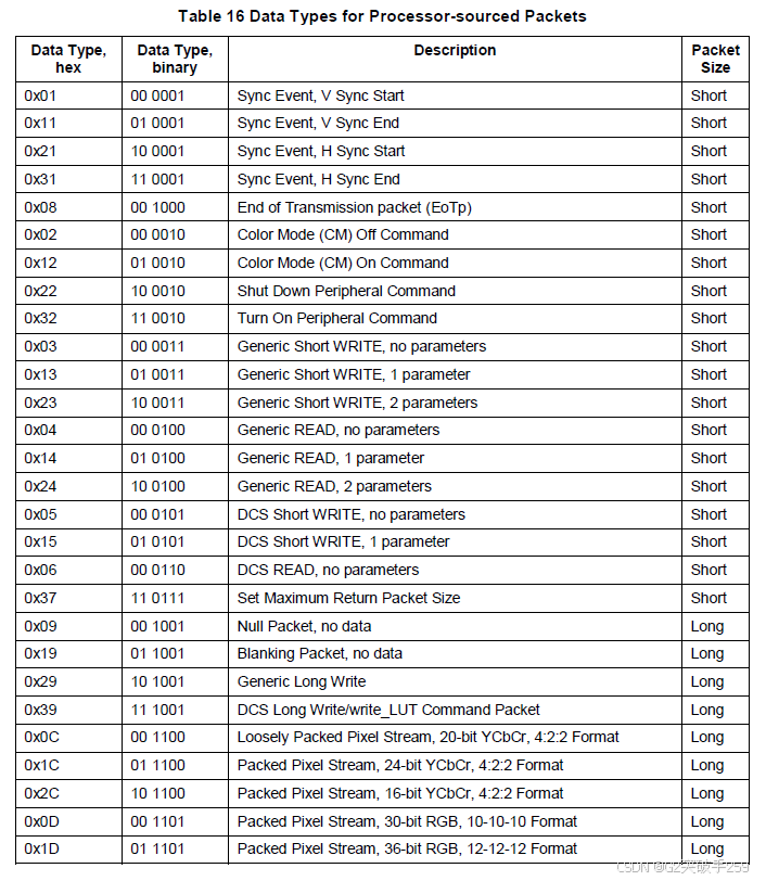
Processor to Peripheral Transactions
Detailed Format Description
Sync Event (H Start, H End, V Start, V End), Data Type = XX 0001 (0xX1)Sync events are short data packets, thus they can accurately represent the timing of events such as the start and end of sync pulses. Since “start” and “end” are independent and distinct events, the length of the sync pulse and its position relative to active pixel data, such as front and back porch display times, can be accurately conveyed to the peripheral device. The sync events are defined as follows:
- Data Type = 00 0001 (0x01) V Sync Start
- Data Type = 01 0001 (0x11) V Sync End
- Data Type = 10 0001 (0x21) H Sync Start
- Data Type = 11 0001 (0x31) H Sync End
To represent timing information as accurately as possible, a V Sync Start event indicates the start of the VSA, which also implies an H Sync Start event for the first line of the VSA. Similarly, a V Sync End event indicates the H Sync Start event for the last line of the VSA. If the host processor source is interlaced video, the horizontal sync timing follows the standard interlaced video conventions of the video format in use, which is beyond the scope of this document. Refer to [CEA01] for timing details of interlaced video formats. The first field of interlaced video follows the same rules to imply H Sync Start. The peripheral (display) should not imply H Sync Start during V Sync Start and V Sync End times when receiving the second video field of interlaced video.If accurate pulse length information needs to be conveyed, sync events should occur in pairs, V Sync Start and V Sync End. Alternatively, if only a single time point (event) is needed, a single sync event (usually Sync Start) can be transmitted to the peripheral. Sync events can be connected with blanking packets to accurately convey inter-line timing and avoid the overhead of switching each event between LPS and HS. However, note that keeping the data line in HS mode incurs power loss.The display module does not require traditional sync/blanking/pixel timing and should transmit pixel data in a high-speed burst mode, then place the bus in low-power mode to reduce power consumption. The recommended burst size is a scan line of pixels (one line of data), which can be temporarily stored in a line buffer on the display module.Sync Event PayloadUsing sync event payloads in short data packets may limit the information sent from the host processor to the display peripheral. This technique is useful for single-byte payloads, especially when effects may apply to the start or end of a frame, and using DCS Short WRITE may be undesirable or unsupported.The data 0 payload of the V Sync Start event should indicate whether there is a special data payload. If Data 0 = 0x00, the peripheral may ignore the contents of the remaining payload bytes. If any bit of Data 0 is non-zero, the peripheral will interpret the contents of Data 1 payload based on the context defined in the table.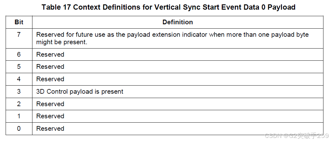 Video ModeUnder 3D control, DSI supports using display peripherals to view stereoscopic images in Video Mode. The method of data transmission to the display peripheral should specify the short data packet Data 1 payload in VSS at the start of the frame. The host processor should send 3D control information each time the 3D control information changes, or more frequently as specified in the display peripheral data sheet. The table summarizes the bits of Data 1 payload.
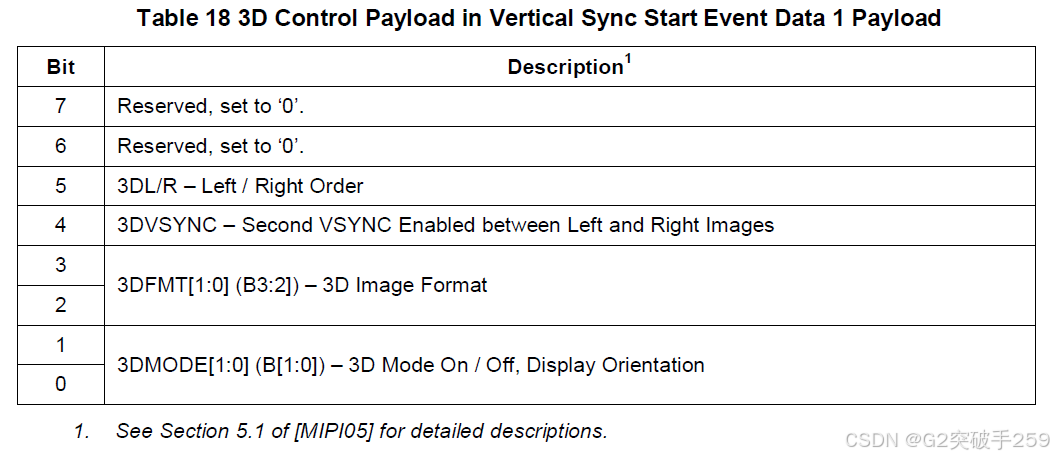 EoTp, Data Type = 00 1000 (0x08)This short data packet is used to indicate the end of HS transmission to the data link layer. Therefore, detecting the end of HS transmission can be decoupled from physical layer characteristics. [MIPI04] defines an EoT sequence consisting of a series of 1s or 0s, depending on the last bit of the last packet in the HS transmission. Due to potential errors, the EoT sequence may be misinterpreted as valid data types. Although EoT errors are not expected to occur frequently, adding this packet will enhance the overall reliability of the system.Devices compliant with earlier versions of the DSI specification do not support EoTp generation or detection. Hosts or peripherals compliant with this revision of the DSI specification should include the capability to support EoTp. Devices should also provide implementation-specific methods to enable and disable this feature to ensure interoperability with earlier DSI devices that do not support EoTp.The primary goal of EoTp is to enhance the overall robustness of the system in HS transmission mode. Therefore, the DSI transmitter should not generate EoTp when transmitting in LP mode. The DSI receiver’s data link layer should detect and interpret the arriving EoTp, regardless of the transmission mode (HS or LP mode), to decouple from the physical layer. The table describes how DSI mandates EoTp support for different transmission and reception modes.
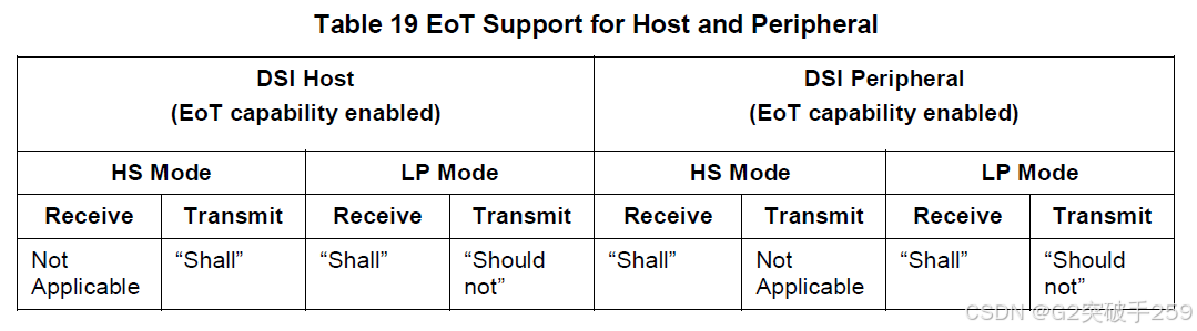 The term “shall” is used to indicate a mandatory requirement that must be strictly adhered to for compliance with the standard, with no deviation allowed.The term “should” is used to indicate that among several possibilities, one is recommended as particularly suitable, without mentioning or excluding other possibilities; or that a certain course of action is preferred but not necessarily required; or that a certain behavior is discouraged but not prohibited.Unlike other DSI packets, EoTp has the following fixed format:
- Data Type = DI [5:0] = 0b001000
- Virtual Channel = DI [7:6] = 0b00
- Payload Data [15:0] = 0x0F0F
- ECC [7:0] = 0x01
The virtual channel identifier associated with EoTp is fixed to 0, regardless of how many different virtual channels exist in the same transmission. For multi-channel systems, EoTp bytes are distributed across multiple channels.Color Mode Off Command, Data Type = 00 0010 (0x02)Color Mode Off is a short data packet command used to return the Video Mode display module from low color mode to normal display state.Color Mode On Command, Data Type = 01 0010 (0x12)Color Mode On is a short data packet command used to switch the Video Mode display module to low color mode to save power.Shutdown Peripheral Command, Data Type = 10 0010 (0x22)Shutdown Peripheral command is a short data packet command used to turn off the display of the Video Mode display module to save power. Note that to receive open or wake commands, the interface must remain powered.Turn On Peripheral Command, Data Type = 11 0010 (0x32)Turn On Peripheral command is a short data packet command used to turn on the display of the Video Mode display module for normal display.Generic Short WRITE Packet with 0, 1, or 2 parameters, Data Types = 00 0011 (0x03), 01 0011 (0x13), 10 0011 (0x23), RespectivelyGeneric Short WRITE command is a type of short data packet used to send generic data to peripherals. The format and interpretation of the contents of this packet are beyond the scope of this document. System designers are responsible for ensuring that both the host processor and the peripheral agree on the format and interpretation of this data.The complete packet length should be four bytes, including one ECC byte. The MSB of the data type, bit[5:4], indicates the number of valid parameters (0, 1, or 2). For single-byte parameters, the parameter will be sent in the first data byte following the DI byte, and the second data byte will be set to 0x00.Generic READ Request with 0, 1, or 2 Parameters, Data Types = 00 0100 (0x04), 01 0100 (0x14), 10 0100 (0x24), RespectivelyGeneric READ Request is a short data packet used to request data from the peripheral. The format and interpretation of the parameters of this packet, as well as the returned data, are beyond the scope of this document. System designers are responsible for ensuring that both the host processor and the peripheral agree on the format and interpretation of this data.The returned data can be in short data packet format or long data packet format. Note that the command to set the maximum return packet size limits the size of the returned packet to prevent buffer overflow when the host processor receives data from the peripheral. If the returned data block exceeds the specified maximum return packet size, the read response will require multiple transmissions. If the requested data block exceeds the maximum packet size, the host processor will send multiple generic read request commands in separate transmissions.The complete packet length should be four bytes, including one ECC byte. The MSB of the data type, bit[5:4], indicates the number of valid parameters (0, 1, or 2). For single-byte parameters, the parameter will be sent in the first data byte following the DI byte, and the second data byte will be set to 0x00.Since this is a read command, BTA should be asserted by the host processor after this request.The peripheral should respond to the generic read request in one of the following ways:
- If the peripheral detects an error, it will send an acknowledgment and an error report. If an ECC error is detected in the request and corrected, the peripheral will send the requested READ data packet, followed by an acknowledgment and error report data packet in the same transmission.
- If the peripheral does not detect an error, it will send the requested READ packet (short packet or long packet), along with the appropriate ECC and Checksum (if Checksum is enabled).
The generic read request should be the only or last packet of the transmission. After the transmission, the host processor sends BTA. After transferring control of the bus to the peripheral, the host processor will expect the peripheral to send the appropriate response packet and then return bus ownership to the host processor.DCS CommandsDCS is a standardized command set for Command Mode display modules.For DCS short commands, the first byte after the data identifier byte is the DCS command byte. If the DCS command does not require parameters, the second valid payload byte should be 0x00.If a DCS command requires multiple parameters, the command should be sent as a long data packet type.DCS Short Write Command, 0 or 1 parameter, Data Types = 00 0101 (0x05), 01 0101 (0x15), RespectivelyDCS Short Write command is used to write a single data byte to the peripheral (such as a display module). The packet consists of a Data ID byte, a DCS Write command byte, an optional parameter byte, and an ECC byte. If there is a valid parameter byte, the data type bit 4 is set to 1; if there is no valid parameter byte, it is set to 0. If no parameters are needed, the parameter byte should be 0x00. If the DCS Short Write command is sent to a bidirectional peripheral followed by BTA, the peripheral should respond with an ACK trigger message unless an error is detected in the transmission from the host to the peripheral. If the peripheral detects an error in the transmission, it should respond with an acknowledgment and an error report. If the peripheral is a unidirectional DSI Video Mode display, it should ignore BTA.DCS Read Request, No Parameters, Data Type = 00 0110 (0x06)DCS READ command is used to request data from the display module. This packet is a short packet consisting of a Data ID byte, a DCS Read command, a byte set to 0x00, and an ECC byte. Since this is a read command, BTA should be asserted by the host processor after the transmission is complete. Depending on the READ type requested in the DCS command byte, the peripheral can respond with either a DCS short read response or a DCS long read response.In the case of a DCS long read response, if the returned data block exceeds the specified maximum return packet size, the read response may consist of multiple packets. In this case, the host processor should send multiple DCS read request commands to transmit the complete data block.The peripheral should respond to the DCS READ request in one of the following ways:
- If the peripheral detects an error, it will send an acknowledgment and an error report. If an ECC error is detected in the request and corrected, the peripheral will send the requested READ data packet, followed by an acknowledgment and error report data packet in the same transmission.
- If the peripheral does not detect an error, it will send the requested READ packet (short packet or long packet), along with the appropriate ECC and Checksum, if either or both features are enabled.
The DCS read request packet should be the only or last packet of the transmission. After the transmission, the host processor sends BTA. After transferring control of the bus to the peripheral, the host processor will expect the peripheral to send the appropriate response packet and then return bus ownership to the host processor.DCS Long Write / write_LUT Command, Data Type = 11 1001 (0x39) (0x39)DCS Long Write/write_LUT command is used to send larger data blocks to the display module executing the Display Command Set.The packet consists of a DI byte, two bytes of WC, an ECC byte, a DCS command byte, a payload of length WC minus one byte, and a two-byte checksum (CRC).Set Maximum Return Packet Size, Data Type = 11 0111 (0x37)The maximum return packet size is a four-byte command packet (including ECC) that specifies the maximum size of the payload in long packets transmitted back from the peripheral to the host processor. The byte order for setting the maximum return packet size is: Data ID, two-byte value for maximum return packet size, ECC byte. Note that the two-byte value is transmitted with the LS byte first. Peripherals with unidirectional DSI interfaces should ignore this command.During power-up or reset sequences, the maximum return packet size should be set by the peripheral to a default value of 1. This parameter should be set by the host processor to the desired value in the initialization routine before normal operation begins.Null Packet (Long), Data Type = 00 1001 (0x09)A Null Packet is a mechanism to keep the serial data channel in high-speed mode while sending virtual data. This is a long data packet. Like all packets, its content should be an integer byte.A Null Packet consists of a DI byte, two bytes of WC, an ECC byte, and a “null” payload of WC bytes, ending with a two-byte checksum. The actual data value sent is irrelevant, as the peripheral does not capture or store the data. However, ECC and Checksum need to be generated and transmitted to the peripheral.Blanking Packet (Long), Data Type = 01 1001 (0x19)The Blanking Packet is used to convey blanking timing information in long data packets. Typically, the packet represents a period of time between active scan lines of a Video Mode display, where traditional display timing is provided by the main processor to the display module. During the blanking period, sync event packets may be interspersed between the blank segments. Like all packets, the Blanking Packet’s content should be an integer byte.The Blanking Packet may contain arbitrary data as payload. The Blanking Packet consists of a DI byte, a two-byte WC, an ECC byte, a payload of length WC bytes, and a two-byte checksum.Generic Long Write, Data Type = 10 1001 (0x29)The Generic Long Write data packet is used to transmit arbitrary data blocks from the host processor to the peripheral in long packet form. The packet consists of a DI byte, a two-byte WC, an ECC byte, a payload of length WC bytes, and a two-byte checksum.Loosely Packed Pixel Stream, 20-bit YCbCr 4:2:2 Format, Data Type = 00 1100 (0x0C)The 20-bit YCbCr 4:2:2 format shown in the figure is a long data packet used to format image data for transmission to the Video Mode display module as 20-bit per pixel. The packet consists of a DI byte, a non-zero two-byte WC, an ECC byte, a payload of length WC bytes, and a two-byte checksum.As shown in the figure, each pixel should have 10-bit corresponding Y-, Cb-, and Cr- components, loosely packed in a 12-bit field. The 10-bit component values should be reasonable so that the highest bits of the 12-bit field b[11:2] retain the 10-bit component values d[9:0]. The least significant bits of the 12-bit field b[1:0] should be 00b. The LSB is sent first, and the MSB is sent last.Using this format, pixel boundaries align with certain byte boundaries. The value in WC (payload size in bytes) should be any non-zero value divisible by 6. The allowed values for WC = {6,12,18, …65 532}.Packed Pixel Stream, 24-bit YCbCr 4:2:2 Format, Data Type = 01 1100 (0x1C)The 24-bit YCbCr 4:2:2 format shown in the figure is a long data packet used to transmit 24-bit image data per pixel to the Video Mode display module. The packet consists of a DI byte, a non-zero two-byte WC, an ECC byte, a payload of length WC bytes, and a two-byte checksum.As shown in the figure, each pixel should have 12-bit corresponding Y-, Cb-, and Cr- components. The LSB is sent first, and the MSB is sent last.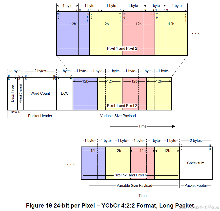 Using this format, pixel boundaries align with certain byte boundaries. The value in WC (payload size in bytes) should be any non-zero value divisible by 6. The allowed values for WC = {6,12,18, …65 532}.Packed Pixel Stream, 16-bit YCbCr 4:2:2 Format, Data Type = 10 1100 (0x2C)The 16-bit YCbCr 4:2:2 format shown in the figure is a long data packet used to transmit 16-bit image data per pixel to the Video Mode display module. The packet consists of a DI byte, a non-zero two-byte WC, an ECC byte, a payload of length WC bytes, and a two-byte checksum.As shown in the figure, each pixel should have 8-bit corresponding Y-, Cb-, and Cr- components. The LSB is sent first, and the MSB is sent last.
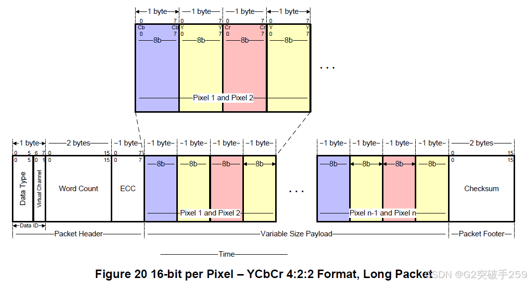 Using this format, pixel boundaries align with certain byte boundaries. The value in WC (payload size in bytes) should be any non-zero value divisible by 4. The allowed values for WC = {4,8,12, …65 532}.Packed Pixel Stream, 30-bit Format, Long Packet, Data Type = 00 1101 (0x0D)The packed pixel stream 30-bit format shown in the figure is a long data packet used to transmit 30-bit image data per pixel to the Video Mode display module. The packet consists of a DI byte, a non-zero two-byte WC, an ECC byte, a payload of length WC bytes, and a two-byte checksum. The pixel format consists of red (10-bit), green (10-bit), and blue (10-bit). The LSB is sent first, and the MSB is sent last.
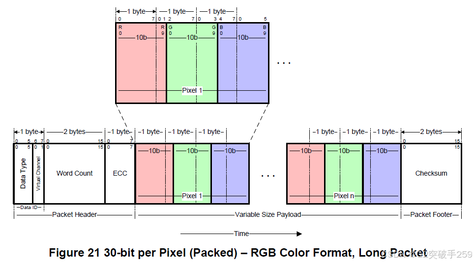 This format uses the sRGB color space. However, when the color space or related formatting information is explicitly defined by previous display commands, this data type can be applied to other color spaces or use 30-bit data transmission per pixel. For example, future revisions of [MIPI01] may extend the data type to include color spaces other than sRGB. The range and nature of formatting commands are beyond the scope of this document.Using this format, pixel boundaries align with byte boundaries every 4 pixels (15 bytes). The total line width (displayed pixels plus non-displayed pixels) should be a multiple of 15 bytes. However, the value in WC (payload size in bytes) should not be limited to non-zero values divisible by 15.Any trailing bits in the byte that are not fully used by pixel data should be zero. For example, if the pixel data is 0b1111111111 1111111111 1111111111, the fourth byte value would be 0x3F. The entire packet VC = 0b00 would be 0x0D 01 00 1E FF FF FF 3F B4 36.Packed Pixel Stream, 36-bit Format, Long Packet, Data Type = 01 1101 (0x1D)The packed pixel stream 36-bit format shown in the figure is a long data packet used to transmit 36-bit image data per pixel to the Video Mode display module. The packet consists of a DI byte, a non-zero two-byte WC, an ECC byte, a payload of length WC bytes, and a two-byte checksum. The pixel format consists of red (12-bit), green (12-bit), and blue (12-bit). The LSB is sent first, and the MSB is sent last.
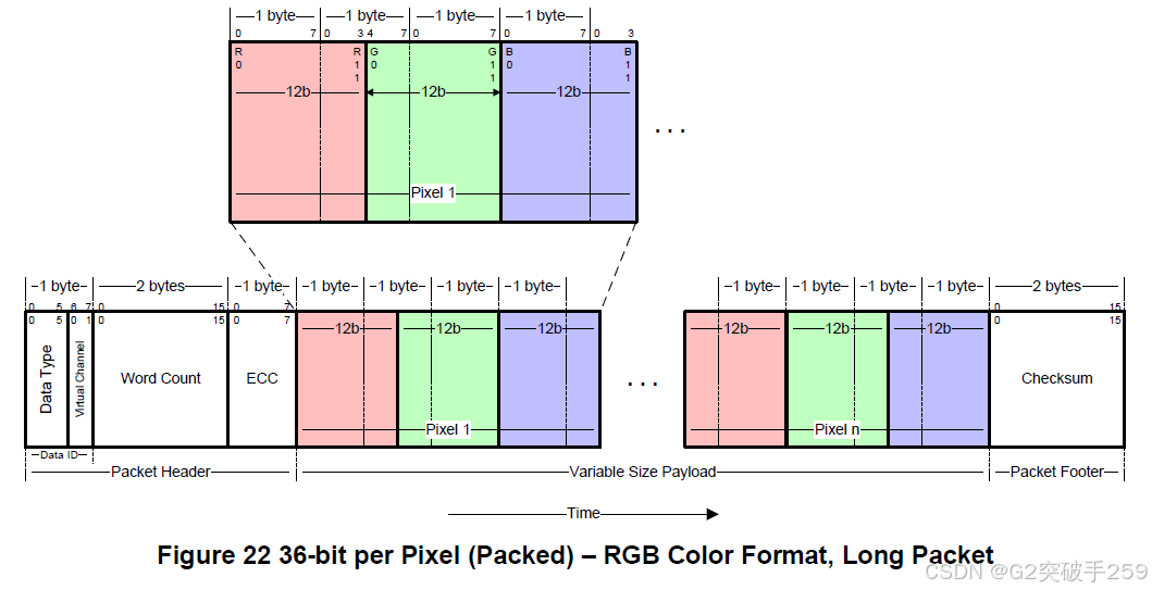 This format uses the sRGB color space. However, when the color space or related formatting information is explicitly defined by previous display commands, this data type can be applied to other color spaces or use 36-bit data transmission per pixel. For example, future revisions of [MIPI01] may extend the data type to include color spaces other than sRGB. The range and nature of formatting commands are beyond the scope of this document.Using this format, pixel boundaries align with byte boundaries every 2 pixels (9 bytes). The total line width (displayed pixels plus non-displayed pixels) should be a multiple of 9 bytes. However, the value in WC (payload size in bytes) should not be limited to non-zero values divisible by 9.Any trailing bits in the byte that are not fully used by pixel data should be zero. For example, if the pixel RGB value is 0b111111111111 111111111111 111111111111, the fifth byte value would be 0x0F. The entire packet VC = 0b00 would be 0x1D 01 00 0D FF FF FF FF 0F 4C 1C.Packed Pixel Stream, 12-bit YCbCr 4:2:0 Format, Data Type = 11 1101 (0x3D) 12-bit YCbCr 4:2:0 format is a long data packet used to transmit 12-bit image data per pixel to the Video Mode display module. The packet consists of a DI byte, a non-zero two-byte WC, an ECC byte, a payload of length WC bytes, and a two-byte checksum.Each pixel should have 8-bit corresponding Y-, Cb-, and Cr- components. The LSB is sent first, and the MSB is sent last. The Cb- and Y- components are sent on odd rows, as shown, while the Cr- and Y- components are sent on even rows, as shown.
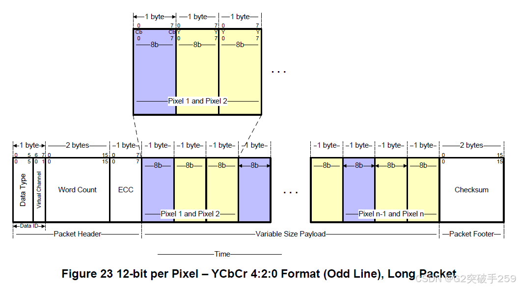
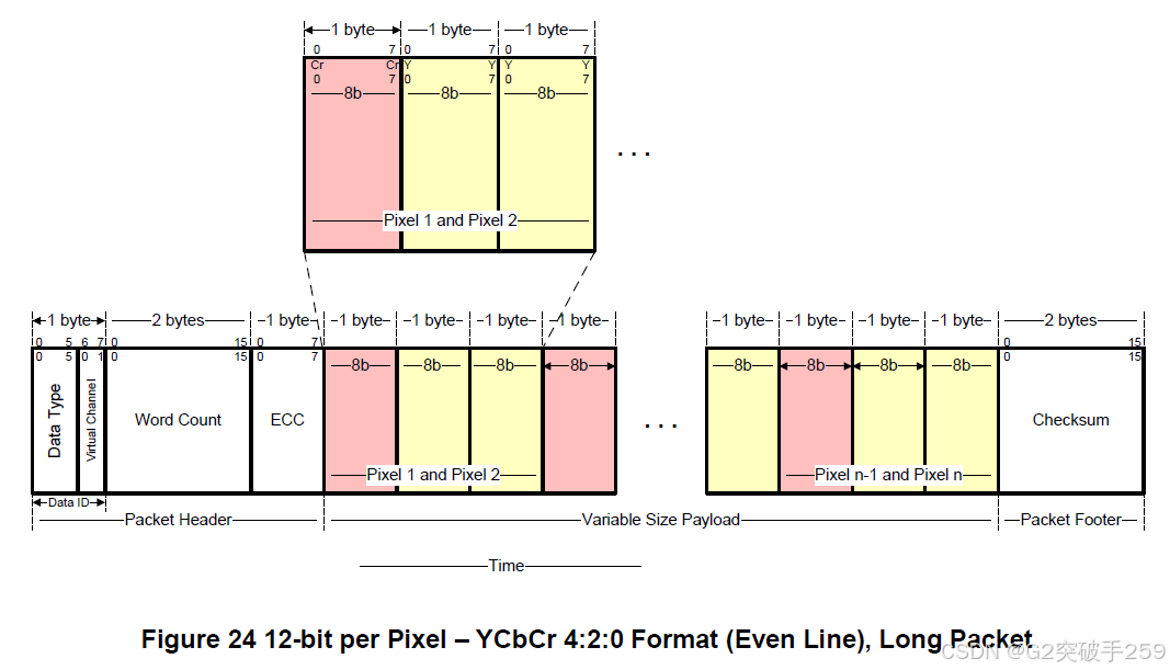 The value in WC (payload size in bytes) should be any non-zero value divisible by 3. The allowed values for WC = {3,6,9, …65 535}.Packed Pixel Stream, 16-bit Format, Long Packet, Data Type = 00 1110 (0x0E)The packed pixel stream 16-bit format shown in the figure is a long data packet used to transmit 16-bit image data per pixel to the Video Mode display module. The packet consists of a DI byte, a non-zero two-byte WC, an ECC byte, a payload of length WC bytes, and a two-byte checksum. The pixel format consists of red (5-bit), green (6-bit), and blue (5-bit). Note that the “Green” component is split into two bytes. The LSB is sent first, and the MSB is sent last.
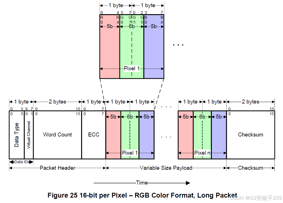 Using this format, pixel boundaries align with byte boundaries every two bytes. The total line width (displayed pixels plus non-displayed pixels) should be a multiple of two bytes.Typically, display modules do not have their own frame buffers, so all image data should be provided by the host processor at a sufficiently high rate to avoid flickering or other visible artifacts.Packed Pixel Stream, 18-bit Format, Long Packet, Data Type = 01 1110 (0x1E)The packed pixel stream 18-bit format shown in the figure is a long data packet used to transmit 18-bit image data per pixel to the Video Mode display module. The packet consists of a DI byte, a non-zero two-byte WC, an ECC byte, a payload of length WC bytes, and a two-byte checksum. The pixel format consists of red (6-bit), green (6-bit), and blue (6-bit). The LSB is sent first, and the MSB is sent last.Note that pixel boundaries align with byte boundaries every 4 pixels (9 bytes). Preferably, display modules using this format have a horizontal range (width in pixels) that is divisible by 4, so that no partial bytes are retained at the end of the displayed line data. If the active (display) horizontal width is not a multiple of 4 pixels, the transmitter should send additional padding pixels at the end of the display line to make the transmission width a multiple of 4 pixels. When refreshing the display device, the receiving peripheral should not display the padding pixels. For example, if the display device has an active display width of 399 pixels, the transmitter should send 400 pixels in one or more packets. The receiver should display the first 399 pixels and discard the last pixel transmitted.Using this format, the total line width (displayed pixels plus non-displayed pixels) should be a multiple of 4 pixels (9 bytes).Pixel Stream, 18-bit Format in Three Bytes, Long Packet, Data Type = 10 1110 (0x2E)In the 18-bit pixel loosely packed format, each R, G, or B color component is 6-bit but is shifted to the high significant bits of the byte, so that the effective pixel bits occupy bits [7:2] of each byte, as shown in the figure. The bits [1:0] of each valid payload byte representing active pixels are ignored. Therefore, each pixel requires three bytes when transmitted through the link. This requires more bandwidth than the “packed” format but requires less shifting and multiplexing logic in the packing and unpacking functions at both ends of the link.
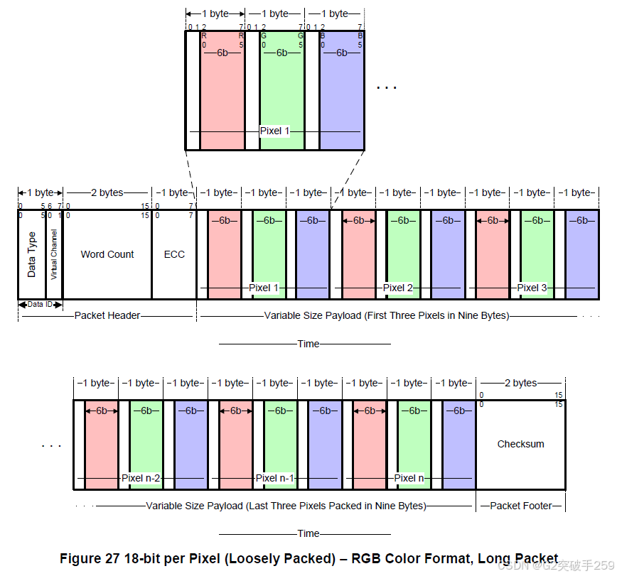 This format is used to transmit 18-bit image data per pixel to the Video Mode display module. The packet consists of a DI byte, a non-zero two-byte WC, an ECC byte, a payload of length WC bytes, and a two-byte checksum. The pixel format consists of red (6-bit), green (6-bit), and blue (6-bit). The LSB is sent first, and the MSB is sent last.Using this format, pixel boundaries align with byte boundaries every three bytes. The total line width (displayed pixels plus non-displayed pixels) should be a multiple of three bytes.Packed Pixel Stream, 24-bit Format, Long Packet, Data Type = 11 1110 (0x3E)The packed pixel stream 24-bit format shown in the figure is a long data packet used to transmit 24-bit image data per pixel to the Video Mode display module. The packet consists of a DI byte, a non-zero two-byte WC, an ECC byte, a payload of length WC bytes, and a two-byte checksum. The pixel format consists of red (8-bit), green (8-bit), and blue (8-bit). Each color component occupies one byte in the pixel stream; no component is split across byte boundaries. The LSB is sent first, and the MSB is sent last.
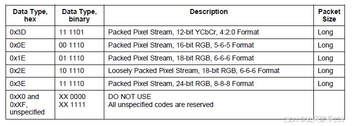
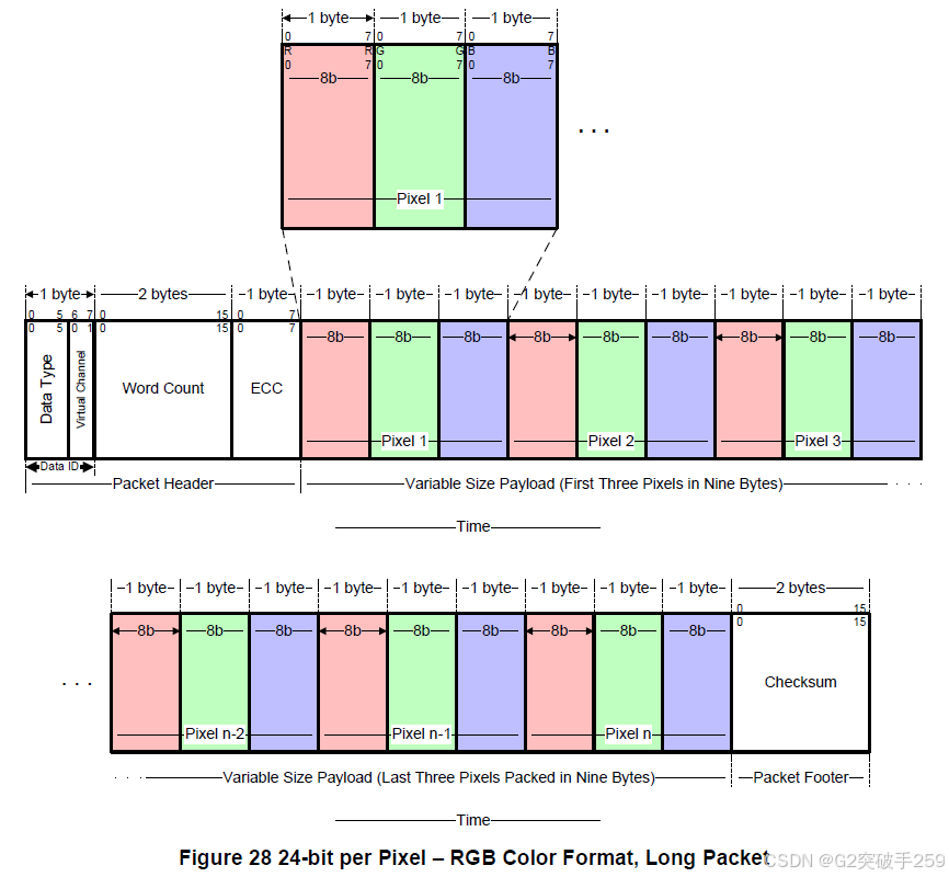 Using this format, pixel boundaries align with byte boundaries every three bytes. The total line width (displayed pixels plus non-displayed pixels) should be a multiple of three bytes.DO NOT USE and Reserved Data TypesData type encodings with 4 LSBs = 0000 or 1111 cannot be used. All other unspecified data type encodings are reserved.Note that the DT encoding is specified so that all data types have at least one 0-1 or 1-0 transition in the four DT bits [3:0]. This ensures a transition between the first four bits of the serial data stream of each packet. The DSI protocol or PHY can use this information to quickly determine whether the next bit after each packet ends represents the start of a new packet (with a transition within 4 bits) or an EoT sequence (with at least 4 bits without a transition).
Recommended Past Articles
|
|||
|
|||
|

Niuxin Semiconductor (Shenzhen) Co., Ltd. (referred to as “Niuxin Semiconductor”) was established in 2020, focusing on the development and licensing of interface IP, and providing related overall solutions, aiming to become a global leading IP supplier.
Niuxin Semiconductor lays out SerDes, DDR, and other mid-to-high-end interface IP in mainstream advanced processes, with products widely used in consumer electronics, network communication, data storage, artificial intelligence, automotive electronics, medical electronics, and other fields.
In the future, Niuxin Semiconductor will continue to respond to the demands of the IP market, adapt to the continuously evolving interface technologies and increasingly expanding interface interconnection scenarios, empowering various industries in the intelligent era.