1. What are the differences between STM32F1 and F4?
Answer:
Reference: STM32 Development – Introduction to STM32Different cores: F1 uses Cortex-M3 core, while F4 uses Cortex-M4 core;Different clock speeds: F1 has a clock speed of 72MHz, while F4 has a clock speed of 168MHz;Floating-point operations: F1 lacks a floating-point unit, while F4 has one;Functional performance: F4 has richer peripherals and stronger functionality compared to F1, such as GPIO toggle rates, pull-up/pull-down resistor configurations, ADC precision, etc.;Memory size: F1 has a maximum internal SRAM of 64K, while F4 has 192K (112+64+16).
2. Can you describe the STM32 startup process?
Answer:
Reference: STM32 Development – Startup ProcessSet the Boot pin to find the initial addressInitialize the stack pointer __initial_spPoint to the reset program Reset_HandlerSet the exception interrupt HardFault_HandlerSet the system clock SystemInitCall the C library function _main
3. Can you describe GPIO?
Answer:
Reference: STM32 Development – Detailed Explanation of GPIO8 working modes of GPIO (gpio_init.GPIO_Mode):(1) GPIO_Mode_AIN Analog Input(2) GPIO_Mode_IN_FLOATING Floating Input(3) GPIO_Mode_IPD Pull-down Input(4) GPIO_Mode_IPU Pull-up Input(5) GPIO_Mode_Out_OD Open Drain Output(6) GPIO_Mode_Out_PP Push-Pull Output(7) GPIO_Mode_AF_OD Alternate Function Open Drain Output(8) GPIO_Mode_AF_PP Alternate Function Push-Pull Output
APB2Responsible for AD, I/O, Advanced TIM, Serial Port 1.APB1Responsible for DA, USB, SPI, I2C, CAN, Serial Ports 2, 3, 4, 5, General TIM, PWR
GPIO Block Diagram Analysis:Reference: STM32 – Detailed Explanation of GPIO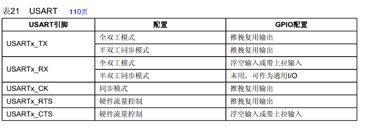 4. UART
-
Question 1: Can you introduce serial communication methods? Synchronous communication: I2C half-duplex, SPI full-duplex; Asynchronous communication: RS485 half-duplex, RS232 full-duplex.
-
Question 2: How to configure the serial port?The general steps for serial port configuration can be summarized as follows: (1) Enable serial port clock, enable GPIO clock (2) Reset the serial port (3) Set GPIO port mode TX’s GPIO working mode to: GPIO_Mode_AF_PP; // Alternate Function Push-Pull Output RX’s GPIO working mode to: GPIO_Mode_IN_FLOATING; // Floating Input (4) Serial port parameter initialization mainly includes: baud rate setting (115200), 8 data bits, 1 stop bit, no parity bit, no hardware flow control, transmit/receive mode. (5) Enable interrupts and initialize NVIC (if interrupts need to be enabled, this step is necessary) (6) Enable the serial port (7) Write the interrupt handler function.
-
Question 3: What are the main features of USART?(1) Full-duplex operation (independent reception and transmission of data); (2) In synchronous operation, can synchronize with master clock or slave clock; (3) Independent high-precision baud rate generator, does not occupy timer/counter; (4) Supports 5, 6, 7, 8, and 9 data bits, 1 or 2 stop bits in serial data frame structure; (5) Hardware-supported parity bit generation and checking; (6) Data overflow detection; (7) Frame error detection; (8) Includes error start bit detection noise filter and digital low-pass filter; (9) Three completely independent interrupts, TX transmission complete, TX data register empty, RX reception complete; (10) Supports multi-device communication mode; (11) Supports double-speed asynchronous communication mode.
Answer:
Reference: STM32 Development – Detailed Explanation of Serial PortApplication scenarios: GPS, Bluetooth, 4G modules
5. I2C
-
Question 1: What are the three types of signals during data transmission on the I2C bus?(1) Start signal: When SCL is high, SDA transitions from high to low, starting data transmission. (2) Stop signal: When SCL is high, SDA transitions from low to high, ending data transmission. (3) Acknowledge signal: The receiving IC sends a specific low-level pulse to the transmitting IC after receiving 8 bits of data, indicating that the data has been received. The CPU sends a signal to the controlled unit and waits for the controlled unit to send an acknowledgment signal. After receiving the acknowledgment signal, the CPU decides whether to continue transmitting signals based on the actual situation. If no acknowledgment signal is received, it is judged that the controlled unit has failed.
-
Question 2: How to configure the I2C master mode port?Hardware mode: Alternate Function Open Drain Output, neither pull-up nor pull-down. (Fast mode: 400 Kbit/s) Software simulation: Push-Pull Output, configure pull-up resistors.
-
Question 3: What is the I2C arbitration mechanism?Reference: S5PV210 Development – How Much Do You Know About I2C? (Part 3)The I2C arbitration mechanism is straightforward once you understand the “wired-AND” principle. In simple terms, it follows the principle of “low level priority”, meaning whoever sends a low level first will gain control of the bus.
Answer:
Reference: STM32 Development – PMIC, Detailed Explanation of I2CHardware mode: Has communication rate settings/* STM32 I2C Fast Mode */#define I2C_Speed 400000
/* Communication rate */I2C_InitStructure.I2C_ClockSpeed = I2C_Speed;
Software simulation: No communication rate set, how to calculate it?By using the I2C bus bit delay function i2c_Delay:
static void i2c_Delay(void)
{
    uint8_t i;

    /*
        The following times were obtained through testing with the Anfu Lai AX-Pro logic analyzer.
        When the CPU frequency is 72MHz, running in internal Flash, MDK project not optimized
        When the loop count is 10, SCL frequency = 205KHz
        When the loop count is 7, SCL frequency = 347KHz, SCL high time 1.5us, SCL low time 2.87us
        When the loop count is 5, SCL frequency = 421KHz, SCL high time 1.25us, SCL low time 2.375us

        IAR project compilation efficiency is high, cannot be set to 7
    */
    for (i = 0; i < 10; i++);
}
Application scenarios: PMIC, accelerometers, gyroscopes
6. SPI
-
Question 1: How many lines does SPI need?SPI interface generally uses 4 lines for communication: MISO master device data input, slave device data output. MOSI master device data output, slave device data input. SCLK clock signal generated by the master device. CS slave device chip select signal controlled by the master device.
-
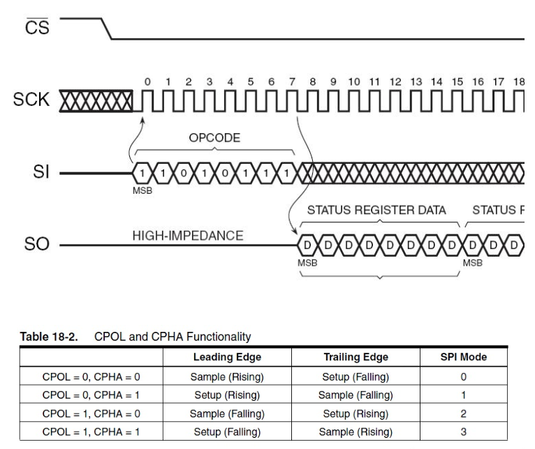
Question 2: What are the four modes of SPI communication?SPI has four working modes, differing in SCLK, specifically determined by CPOL and CPHA. (1)CPOL: (Clock Polarity), clock polarity:SPI’s CPOL indicates whether the level of SCLK is low (0) or high (1) when idle: CPOL=0 means the clock is low when idle, so when SCLK is active, it is high, known as active-high; CPOL=1 means the clock is high when idle, so when SCLK is active, it is low, known as active-low;
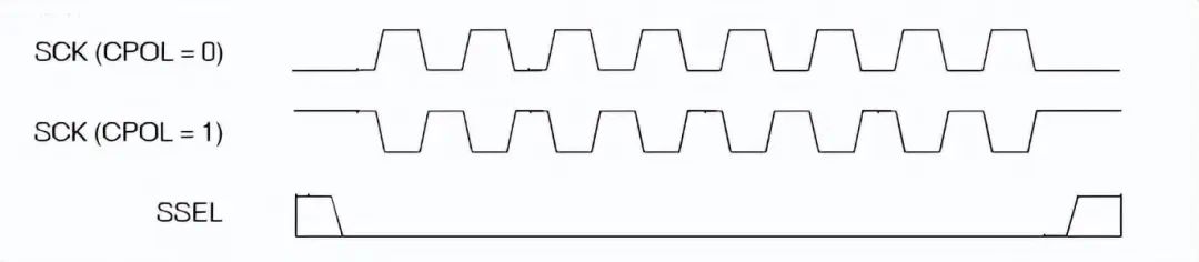
(2)CPHA: (Clock Phase), clock phase:Phase corresponds to the data sampling edge, whether it is the first edge or the second edge,0 corresponds to the first edge, 1 corresponds to the second edge. For:CPHA=0 means the first edge:For CPOL=0, when idle it is low, the first edge is from low to high, so it is the rising edge;For CPOL=1, when idle it is high, the first edge is from high to low, so it is the falling edge;CPHA=1 means the second edge:For CPOL=0, when idle it is low, the second edge is from high to low, so it is the falling edge;For CPOL=1, when idle it is high, the first edge is from low to high, so it is the rising edge;
-
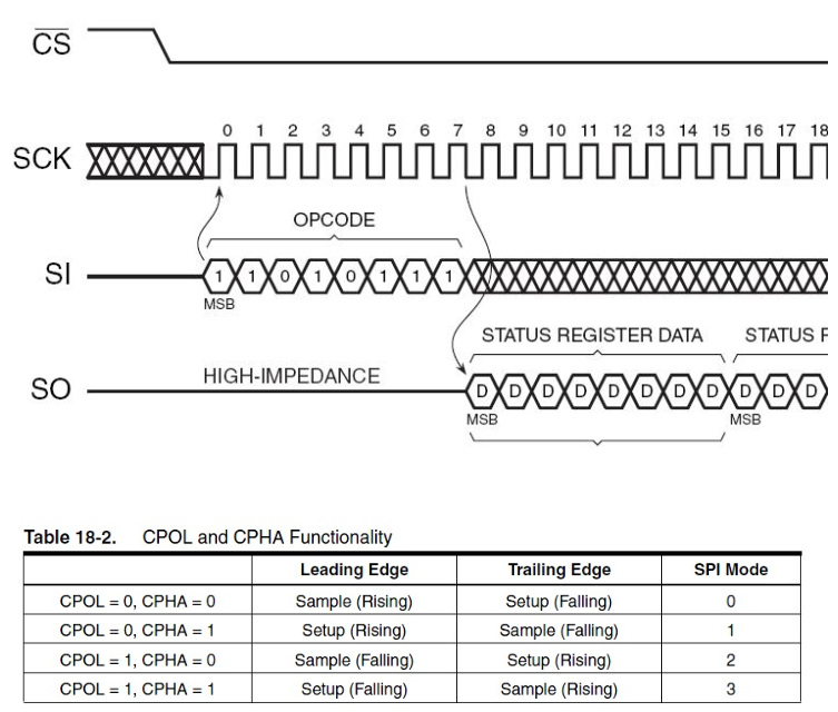
Question 3: How to determine which mode to use?(1) First confirm the SCLK polarity required by the slave, whether it is low or high when not working, thus confirming CPOL as 0 or 1. Looking at the schematic, we set the idle state of the serial synchronous clock to high, so we choose SPI_CPOL_High.That is, CPOL is 1(2) Then confirm from the slave chip datasheet’s timing diagram whether the slave chip samples data on the falling edge or the rising edge of SCLK. To translate: W25Q32JV is accessed via SPI-compatible bus, including four signals: serial clock (CLK), chip select (/CS), serial data input (DI), and serial data output (DO). Standard SPI instructions use the DI input pin to serially write instructions, addresses, or data to the device on the rising edge of CLK. The DO output pin is used to read data or status from the device on the falling edge of CLK. Supports SPI bus operations in mode 0 (0,0) and 3 (1,1). Modes 0 and 3 focus on the normal state of the CLK signal when the SPI bus master is idle, and no data is being transmitted to the serial Flash. For mode 0, the CLK signal is typically low on the falling and rising edges / CS. For mode 3, the CLK signal is typically high on the falling and rising edges of /CS. Since the idle state of the serial synchronous clock is high, we choose the second transition edge, thus selecting SPI_CPHA_2Edge.That is, CPHA is 1Thus, we choose mode 3 (1,1).
Answer:
Reference: STM32 Development – Detailed Explanation of W25Q32 SPI FlashReference: Detailed Explanation of CPOL and CPHA in SPIApplication scenarios: SPI Flash, W25Q32 memory capacity 32Mb (4M x 8), which is 4M byte
7. CAN
-
Question 1: Can you summarize CAN?The CAN controller determines the bus level based on the potential difference between CAN_L and CAN_H. The bus level is divided into dominant and recessive levels, one of which is chosen. The sender sends a message to the receiver by changing the bus level.
-
Question 2: What are the initialization configuration steps for CAN?(1) Configure the multiplexing function of the relevant pins, enable the CAN clock (2) Set the CAN operating mode and baud rate, etc. (CAN initialization loopback mode, baud rate 500Kbps) (3) Set the filter.
-
Question 3: What is the data format for sending CAN data?CanTxMsg TxMessage; TxMessage.StdId=0x12; // Standard Identifier TxMessage.ExtId=0x12; // Set Extended Identifier TxMessage.IDE=CAN_Id_Standard; // Standard Frame TxMessage.RTR=CAN_RTR_Data; // Data Frame TxMessage.DLC=len; // Length of data to be sent 8 bytes for(i=0;i<len;i++) TxMessage.Data[i]=msg[i]; // Data
Answer:
Reference: STM32 Development – Detailed Explanation of CAN Bus
8. DMA
-
Question 1: What is DMA?Direct Memory Access (DMA) is used to provide high-speed data transfer between peripherals and memory or between memory and memory. Data can be moved quickly via DMA without CPU intervention, saving CPU resources for other operations.
-
Question 2: How many DMA transfer modes are there?DMA_Mode_Circular Circular Mode DMA_Mode_Normal Normal Buffer Mode Application scenarios: GPS, Bluetooth, both use circular acquisition, DMA_Mode_Circular mode.
Answer:
Reference: STM32 Development – Detailed Explanation of DMA
A relatively important function is to obtain the current remaining data size, based on the configured receive buffer size minus the current remaining data size,to get the current received data size.
9. Interrupts
-
Question 1: Describe the interrupt handling process?(1) Initialize the interrupt, set the trigger method to rising edge/ falling edge/ dual edge trigger. (2) Trigger the interrupt, enter the interrupt service function.
-
Question 2: How many external interrupts does the STM32 interrupt controller support?The STM32 interrupt controller supports 19 external interrupt/event requests:From the diagram, GPIO pins GPIOx.0~GPIOx.15 (x=A, B, C, D, E, F, G) correspond to interrupt lines 0 ~ 15. The connection method for the other four EXTI lines is as follows: ● EXTI line 16 connected to PVD output ● EXTI line 17 connected to RTC alarm event ● EXTI line 18 connected to USB wake-up event ● EXTI line 19 connected to Ethernet wake-up event (only applicable to interconnect products)Interrupt service function list:IO port external interrupts are allocated only 7 interrupt vectors in the interrupt vector table, meaning only 7 interrupt service functions can be used. EXTI0_IRQHandler EXTI1_IRQHandler EXTI2_IRQHandler EXTI3_IRQHandler EXTI4_IRQHandler EXTI9_5_IRQHandler EXTI15_10_IRQHandler
Answer:
Reference: STM32 Development – Detailed Explanation of External Interrupts
10. How many clock sources does STM32 have?
STM32 has 5 clock sources: HSI, HSE, LSI, LSE, PLL. ① HSI is a high-speed internal clock, RC oscillator, frequency of 8MHz, with low accuracy. ② HSE is a high-speed external clock, can connect quartz/ceramic resonators, or connect external clock sources, frequency range of 4MHz~16MHz. ③ LSI is a low-speed internal clock, RC oscillator, frequency of 40kHz, providing low-power clock. ④ LSE is a low-speed external clock, connected to a quartz crystal with a frequency of 32.768kHz. ⑤ PLL is a phase-locked loop frequency multiplier output, its clock input source can be selected as HSI/2, HSE, or HSE/2. The multiplication factor can be selected from 2 to 16, but its output frequency must not exceed 72MHz.
Answer:
Reference: STM32 Development – Detailed Explanation of Clock System
11. How to write tasks in RTOS? How to switch out this task?
Answer:
A task, also known as athread.UCOS has a task scheduling mechanism,which schedules based on task priority.One is hardware interrupts, then the system will push the current task-related variables onto the stack, then execute the interrupt service program, and return after execution.Another is task switching between tasks, using task scheduling, each task has its own stack, and the same goes for pushing onto the stack, then executing another program, and then popping back.
Not every task is executed in order of priority, but high-priority tasks run exclusively, unless they voluntarily give up execution; otherwise, low-priority tasks cannot preempt them. At the same time, high-priority tasks can reclaim CPU occupancy rights that they have given up for low-priority tasks. Therefore,it is important to insert wait delays between tasks in ucos to allow ucos to switch out and let low-priority tasks execute.
12. What are the communication methods between tasks in UCOSII?
Answer:
In UCOSII, communication between tasks is achieved using semaphores, mailboxes (message mailboxes), and message queues, which are referred to as events, as well as global variables.Semaphore:Reference: Summary of Semaphore Usage in ucosII (Example Explanation)Semaphores are used for:1. Controlling the use rights of shared resources (satisfying mutual exclusion conditions)2. Indicating the occurrence of an event3. Synchronizing the behavior of two tasks
Application example: Mutual exclusion semaphoreAs a mutual exclusion condition, the semaphore is initialized to 1.Goal: When calling the serial port to send a command, it must wait for the return of the “OK” character before sending the next command. Each task may use this sending function, and conflicts must not occur!
Mailbox (message mailbox):
Message queue:Concept:(1) A message queue is essentially an array of mailboxes.(2) Both tasks and interrupts can place a message into the queue, and tasks can retrieve messages from the message queue.(3) The first message to enter the queue is the first to be passed to the task (FIFO).(4) Each message queue has a waiting list for tasks waiting for messages; if there are no messages in the queue, the waiting tasks are suspended until a message arrives.
Application scenarios: Receive buffer in serial port receiving program.Store external events.
13. The project uses a custom protocol; what is its structure?
Answer:
Familiar with the Modbus protocol.The structure is: Frame header (SDTC) + Frame length + Command + Serial number + Data + CRC check.
14. What are the differences between uCOSII and Linux?
Answer:
μC/OS-II is specifically designed for embedded applications in computers,μC/OS-II has characteristics such as high execution efficiency, small footprint, excellent real-time performance, and strong scalability, with the minimum kernel able to be compiled to 2KB.μC/OS-II has been ported to almost all well-known CPUs.Linux is free, secure, stable, and widely used in embedded systems, servers, and home machines.Both μC/OS-II and Linux are suitable for embedded use. However, μC/OS-II is specifically designed for embedded systems, resulting in higher running efficiency and less resource usage.Linux can be used on servers and has a high usage rate. Although Linux was not specifically developed for servers, its open-source nature allows for modifications, making the differences between the two not significant. The most widely used distribution, Red Hat Linux, is a system commonly used on servers.
15. Git code submission
Question: What is the process for submitting code with Git?
Answer:
1. Display modified files in the working path:
$ git status2. Enter the directory of the modified file:
$ cd -3. Display differences with the last submitted version of the file:
$ git diff4. Add all current modifications to the next submission:
$ git add .5. Add relevant function descriptions (use this for the first submission)
$ git commit -sWhere you also need to specify:Function: Function of the modified codeTicket: Corresponding Bug numberNote: Each folder must be submitted again.6. View submitted code
$ tig .7. Do not modify published submission records! (Use this for future submissions)
$ git commit --amendIn command mode:😡 (write file and exit)8. Push to the server
$ git push origin HEAD:refs/for/master16. Comparison of ucosii, ucosiii, and freeRTOS
-
Question 1: Comparison of the three?
Answer:
Comparison of ucosii and freeRTOS:(1) freeRTOS only supports TCP/IP, while uCOSii has extensive support for peripherals such as FS, USB, GUI, CAN, etc. (We need to use CAN for the tbox, so we choose uCOSii)(2) freeRTOS is free for commercial use. uCOSii requires payment for commercial use.(3) For inter-task communication, freeRTOS only supports queues, semaphores, and mutexes. uCOSii supports event flag groups and mailboxes in addition to these.(4) Theoretically, freeRTOS can manage more than 64 tasks, while uCOSii can only manage 64.
Comparison of ucosii and ucosiii:From μC/OS-II to μC/OS-III, what are the differences? There are significant changes. One is that previously there were only 0~63 priorities, and priorities could not be duplicated. Now, several tasks can use the same priority, and time-slice scheduling is supported within the same priority.Secondly, it allows users to dynamically configure real-time operating system kernel resources during program execution, such as tasks, task stacks, semaphores, event flag groups, message queues, message counts, mutex semaphores, memory block partitions, and timers, which can be changed during program execution. This way, users can avoid resource allocation issues during program compilation. Improvements have also been made in resource reuse.In μC/OS-II, the maximum number of tasks is 64, while in version 2.82 and later, it is 256. In μC/OS-III, users can have any number of tasks, semaphores, mutex semaphores, event flags, message lists, timers, and any allocated memory block capacity, limited only by the amount of RAM available to the user’s CPU. This is a significant expansion. (Question: Teacher Shao, is this number fixed at startup, or can it be defined later?) It can be freely defined during configuration, as long as your RAM is sufficient. The fourth point is that many functions have been added, and the functionality is always increasing; everyone can take a look. Originally, these functions were not available in μC/OS-II.
17. Low Power Modes
-
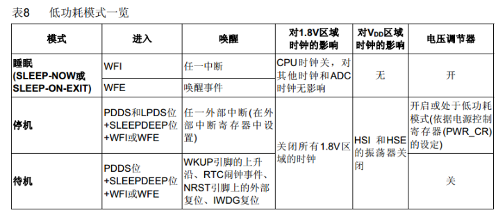
Question 1: What types of low power modes are there? What are the wake-up methods?
Answer:
 18. Internet of Things Architecture
-
Question 1: How many layers are there in the Internet of Things architecture? What functions does each layer perform?
Answer:
The architecture is divided into three layers: the perception layer, the network layer, and the application layer,(1)Perception Layer: Responsible for information collection and information transmission between objects. Information collection technologies include sensors, barcodes and QR codes, RFID radio frequency technology, audio and video, and other multimedia information. Information transmission includes near and far distance data transmission technologies, self-organizing networking technologies, collaborative information processing technologies, and middleware technologies for information collection, etc. The perception layer is the core capability for achieving comprehensive perception in the Internet of Things, and it is a part that urgently needs breakthroughs in key technologies, standardization, and industrialization, focusing on having more precise and comprehensive perception capabilities while solving issues of low power consumption, miniaturization, and low cost.(2)Network Layer: Utilizes wireless and wired networks to encode, authenticate, and transmit collected data. The widely covered mobile communication network is the infrastructure for achieving the Internet of Things, and it is the most standardized, industrially capable, and mature part of the three layers of the Internet of Things, focusing on optimizing and improving for the characteristics of IoT applications, forming a collaborative perception network.(3)Application Layer: Provides rich applications based on the Internet of Things, which is the fundamental goal of IoT development, combining IoT technology with industry information needs to achieve a wide range of intelligent application solutions, focusing on industry integration, development and utilization of information resources, low-cost high-quality solutions, information security assurance, and effective business model development.
19. Memory Management
-
Question 1: What methods are there for memory management in UCOS?
Answer:
The system manages memory partitions through memory control blocks associated with the memory partitions.
Dynamic memory management functions include:Creating dynamic memory partition function OSMemCreate();Requesting memory block function OSMemGet();Releasing memory block function OSMemPut();
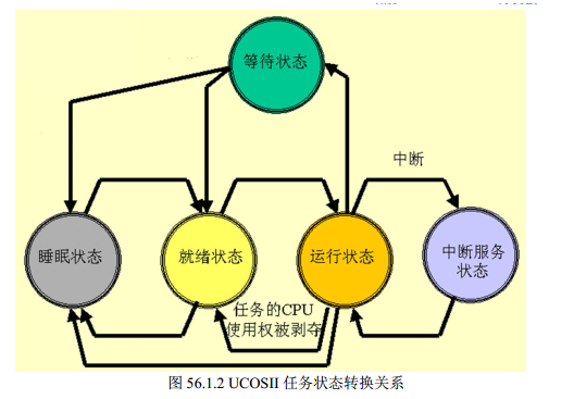
20. What are the task states in Ucos? Draw the relationship diagram between task states.
Answer:
There are 5 states: Sleep state, Ready state, Running state, Waiting state (waiting for a certain event to occur), and Interrupt service state.
UCOSII task’s 5 state transition relationships:
 21. ADC
-
Question 1: Briefly describe the functional characteristics of the STM32 ADC system?(1) 12-bit resolution (2) Automatic calibration (3) Programmable data alignment (conversion results support left or right alignment stored in 16-bit data registers) (4) Single and continuous conversion modes
Reference: STM32 Development – Detailed Explanation of ADC
22. System Clock
-
Question 1: Briefly describe the basic process of setting the system clock?(1) Turn on HSE, wait for it to be ready, then set Flash wait operations. (2) Set AHB, APB1, APB2 division factors, determining their relationship with the system clock. (3) Set the CFGR register to determine the clock source and multiplication factor for PLL (HSE external 8M * 9 times = 72MHz). (4) Enable PLL, switch the system clock source to PLL.
23. HardFault_Handler Processing
-
Question 1: What are the causes?(1) Array out-of-bounds operation; (2) Memory overflow, out-of-bounds access; (3) Stack overflow, program runaway; (4) Interrupt handling errors;
-
Question 2: What is the handling method?(1) Find the address remapping of HardFault_Handler in startup_stm32f10x_cl.s and rewrite it,to jump to the HardFaultHandle function.(2) Print and check registers R0, R1, R2, R3, R12, LR, PC, PSR. (3) Check the Fault status register group (SCB->CFSR and SCB->HFSR)
Reference: STM32 Development – HardFault_Handler ProcessingReference: Cortex-M3 and Cortex-M4 Fault Exception Application – Basic Knowledge
24. TTS Speech Synthesis Method
-
Question 1: What method does sim7600 TTS speech use?
Answer:
(1) Use unicode encoding to synthesize soundAT+CTTS=1,”6B228FCE4F7F75288BED97F3540862107CFB7EDF” The content is “Welcome to the voice synthesis system”, the module sends and receives Chinese SMS using unicode encoding, so it is easy to read the SMS aloud;(2) Directly input text, ordinary characters use ASCII code, Chinese characters use GBK encoding.AT+CTTS=2,”Welcome to the voice synthesis system”
25. Timer
-
Question 1: Given that the STM32 system clock is 72MHz, how to set the relevant registers to achieve a 20ms timer?
Answer:
Reference: STM32 Development – SysTick TimerBy using SysTick_Config(SystemCoreClock / OS_TICKS_PER_SEC)) // 1ms timer
Where:
uint32_t SystemCoreClock         = SYSCLK_FREQ_72MHz;        /*!< System Clock Frequency (Core Clock) */
#define SYSCLK_FREQ_72MHz  72000000
#define OS_TICKS_PER_SEC       1000    /* Set the number of ticks in one second
If 20ms is needed, a global variable can be set, initialized to 20, so that each SysTick interrupts once, this global variable decreases by 1, and when it reaches 0, it means the SysTick has interrupted 20 times, with a time of: 1ms * 20 = 20ms. Thus achieving a 20ms timer.
26. Priority
-
Question 1: How do two tasks with the same priority run?
Answer:
Temporarily elevate the priority of the task obtaining the semaphore to one level higher than the highest priority of all tasks during the use of shared resources, so that this task is not interrupted by other tasks, allowing it to quickly use and release the shared resource, and then restore the original priority of that task after releasing the semaphore.
27. State Machine
-
Question 1: What state machine are you using?
Answer:
Reference: STM32 Development – State Machine and State Transition Logic
Finite State Machine (FSM), also known as finite state automaton.Reference: Detailed Explanation of Finite State Machine FSM and Its Implementation
Assuming the state transitions of the state machine are shown in the table below:
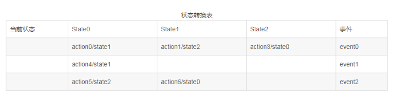
Implementation: (using switch statement)
// Written horizontally
void event0func(void)
{
switch(cur_state)
    {
case State0:
             action0;
             cur_state = State1;
break;
case State1:
             action1;
             cur_state = State2;
break;
case State2:
             action1;
             cur_state = State0;
break;
default:break;
    }
}

void event1func(void)
{
switch(cur_state)
    {
case State0:
             action4;
             cur_state = State1;
break;
default:break;
    }
}

void event2func(void)
{
switch(cur_state)
    {
case State0:
             action5;
             cur_state = State2;
break;
case State1:
             action6;
             cur_state = State0;
break;
default:break;
    }
}
28. Device Selection
-
Question 1: Comparison of STM32F407 VS STM32F103 main functions and resources?
Answer:
Reference: Comparison of STM32F407 VS STM32F103 main functions and resources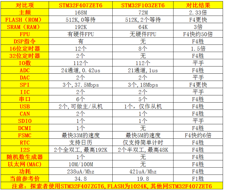


Screenshots of part of the 400G collection electronic books