1. System Architecture Design
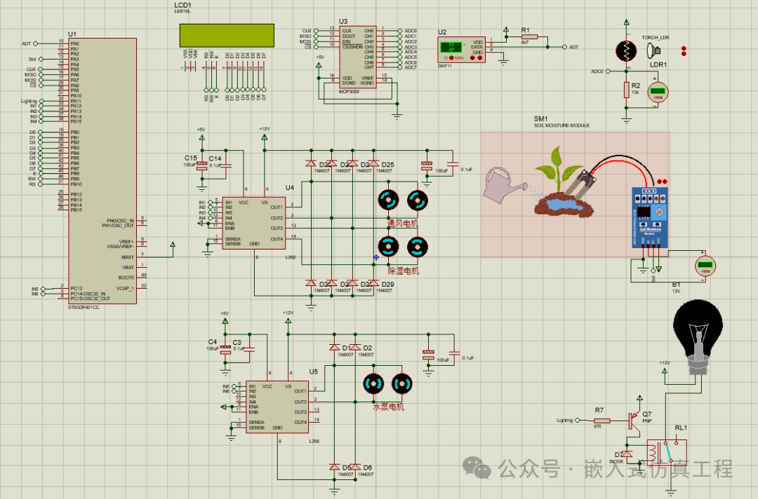
This intelligent greenhouse control system uses the STM32F401CC as the core controller, collecting environmental parameters through multiple sensors and driving actuators for automatic control. The system hardware architecture is as follows:
-
Sensor Module:
-
DHT11 Temperature and Humidity Sensor (PA0)
-
Soil Moisture Sensor (PA3 ADC)
-
LDR Light Sensor (MCP3008 CH0)
Display Module:
-
LM016L LCD Display (PB0-PB10)
Actuators:
-
Ventilation/Dehumidification Motor (L298N Driver, PA14-PA15)
-
Water Pump Motor (Second L298N Driver, PC14-PC15)
-
Lighting (PA11)
Communication Interface:
-
SPI Interface connecting MCP3008 ADC (PA5-PA8)
2. Detailed Configuration of STM32CubeMX
1. Pin Configuration Table
| Pin | Function | Configuration Mode |
|---|---|---|
| PA0 | DHT11 Data Line | GPIO_Input |
| PA3 | Soil Moisture Sensor | ADC1_IN3 |
| PA5 | SPI1_SCK (MCP3008) | SPI1_SCK |
| PA6 | SPI1_MISO (MCP3008) | SPI1_MISO |
| PA7 | SPI1_MOSI (MCP3008) | SPI1_MOSI |
| PA8 | MCP3008 CS | GPIO_Output |
| PB0-PB7 | LCD Data Lines D0-D7 | GPIO_Output |
| PB8 | LCD E | GPIO_Output |
| PB9 | LCD RW | GPIO_Output |
| PB10 | LCD RS | GPIO_Output |
| PA12-15 | L298N IN1-IN4 | GPIO_Output |
| PC14-15 | Water Pump L298N Control | GPIO_Output |
| PA11 | Lighting Control | GPIO_Output |
2. Peripheral Parameter Configuration
-
SPI1 Configuration:
-
Mode: Full-Duplex Master
-
Hardware NSS: Disable
-
Prescaler: 16 (resulting in 2.5MHz clock)
-
Data Size: 8 bits
-
First Bit: MSB First
-
Clock Polarity: Low
-
Clock Phase: 1 Edge
Generate IAR project code.
3. IAR Project Code Implementation
Write the application program and compile to generate HEX file.
#include “main.h”
/* Private includes ———————————————————-*/
/* USER CODE BEGIN Includes */
#include “uart.h”
#include “DHT11.h”
#include “uart.h”
#include “stdio.h”
#include “string.h”
#include “LCD1602.h”
#include “MCP3008.h”
/* USER CODE END Includes */
/* Private typedef ———————————————————–*/
/* USER CODE BEGIN PTD */
/* USER CODE END PTD */
/* Private define ————————————————————*/
/* USER CODE BEGIN PD */
/* USER CODE END PD */
/* Private macro ————————————————————-*/
/* USER CODE BEGIN PM */
/* USER CODE END PM */
/* Private variables ———————————————————*/
SPI_HandleTypeDef hspi1;
UART_HandleTypeDef huart1;
/* USER CODE BEGIN PV */
char textT[100];
char textH[100];
unsigned int DHT11_TEMP; // Declare in main
unsigned int DHT11_HUM; // Declare in main
char texto[100];
MCP3008_SPI spi_mpc3008;
uint16_t adc0;
float result_0;
/* USER CODE END PV */
/* Private function prototypes ———————————————–*/
void SystemClock_Config(void);
static void MX_GPIO_Init(void);
static void MX_USART1_UART_Init(void);
static void MX_SPI1_Init(void);
/* USER CODE BEGIN PFP */
/* USER CODE END PFP */
/* Private user code ———————————————————*/
/* USER CODE BEGIN 0 */
void FAN_ON(void)
{
HAL_GPIO_WritePin (GPIOA, GPIO_PIN_12, GPIO_PIN_RESET);
HAL_GPIO_WritePin (GPIOA, GPIO_PIN_13, GPIO_PIN_SET);
}
void FAN_OFF(void)
{
HAL_GPIO_WritePin (GPIOA, GPIO_PIN_12, GPIO_PIN_RESET);
HAL_GPIO_WritePin (GPIOA, GPIO_PIN_13, GPIO_PIN_RESET);
}
void DehumidificationMotor_ON(void)
{
HAL_GPIO_WritePin (GPIOA, GPIO_PIN_14, GPIO_PIN_RESET);
HAL_GPIO_WritePin (GPIOA, GPIO_PIN_15, GPIO_PIN_SET);
}
void DehumidificationMotor_OFF(void)
{
HAL_GPIO_WritePin (GPIOA, GPIO_PIN_14, GPIO_PIN_RESET);
HAL_GPIO_WritePin (GPIOA, GPIO_PIN_15, GPIO_PIN_RESET);
}
void Lighting_ON(void)
{
HAL_GPIO_WritePin (GPIOA, GPIO_PIN_11, GPIO_PIN_SET);
}
void Lighting_OFF(void)
{
HAL_GPIO_WritePin (GPIOA, GPIO_PIN_11, GPIO_PIN_RESET);
}
void SoilMotor_ON(void)
{
HAL_GPIO_WritePin (GPIOC, GPIO_PIN_13, GPIO_PIN_RESET);
HAL_GPIO_WritePin (GPIOC, GPIO_PIN_14, GPIO_PIN_SET);
}
void SoilMotor_OFF(void)
{
HAL_GPIO_WritePin (GPIOC, GPIO_PIN_13, GPIO_PIN_RESET);
HAL_GPIO_WritePin (GPIOC, GPIO_PIN_14, GPIO_PIN_RESET);
}
4. Proteus Simulation Design
1. Key Component Connections in the Simulation Circuit
-
Sensor Section:
-
DHT11 connected to PA0
-
Soil moisture sensor simulated with a potentiometer, connected to PA3
-
LDR collected through MCP3008 CH0
Display Section:
-
LM016L data lines connected to PB0-PB7
-
Control lines E/RW/RS connected to PB8-PB10
Actuators:
-
L298N drives ventilation/dehumidification motor (PA12-PA15)
-
Second L298N drives water pump (PC14-PC15)
-
Lighting simulated with LED (PA11)
2. Simulation Debugging Techniques
-
Sensor Simulation:
-
Adjust the DHT11 arrow settings for temperature and humidity values to observe changes on the LCD display and the actions of the ventilation and dehumidification motors
-
Adjust the soil sensor arrow to simulate different soil moisture levels and observe the water pump motor action
-
Modify the LDR arrow to change light intensity
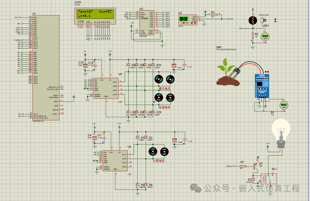
Operation Monitoring:
-
Add voltage probes to observe motor control signals
-
Use a virtual terminal to view debugging information
-
Add charts to record parameter change curves
Fault Testing:
-
Simulate sensor disconnection to check system response
-
Test system response under extreme environmental values
-
Verify interlock logic of each actuator
5. System Optimization Suggestions
-
Increase Software Filtering:
-
Add status indicator lights
-
Use different colored LEDs to indicate system status
-
Flash to indicate alarm status
Introduce PID Control
Add Communication Interfaces
-
Add UART interface to connect to WiFi module
-
Implement remote monitoring via mobile app
This solution fully implements an intelligent greenhouse control system based on STM32F401CC, including sensor data collection, environmental parameter display, and automatic control functions, and verifies the correctness of the system design through Proteus simulation. During actual deployment, control parameters can be adjusted and more functional modules can be expanded according to specific needs.
Welcome to follow (operation reference article: Send a message to the public account), click the blue text at the top “Embedded Simulation Project” or long press to identify the QR code to follow
Reply in the public account
3225
After receiving, the link to this IAR project will be automatically sent