For controlling the LED light, we can imagine the functions of the LED light. The first is the switch, brightness, and color, which are the main three functions. How can we abstract these three functions? Regardless of what the underlying LED device is, we can abstract it using this structure.
As shown below, controlling the LED device certainly requires an initialization function. To control the LED device’s on/off state, we currently set the color of the LED light using a tri-color light, which is not yet supported. The brightness of the LED light can be controlled by providing PWM waves with different duty cycles; this project has not considered that yet.
typedef struct LEDDevice { int which; /* Initialize LED device, return 0 on success */ int (*Init)(struct LEDDevice *ptLEDDevice); /* Control LED device, iStatus values: 1-on, 0-off */ int (*Control)(struct LEDDevice *ptLEDDevice, int iStatus); /* Not implemented */ void (*SetColor)(struct LEDDevice *ptLEDDevice, int iColor); /* Not implemented */ void (*SetBrightness)(struct LEDDevice *ptLEDDevice, int iBrightness);} LEDDevice, *PLEDDevice;Next, we divide the LED device into four layers, as shown in the figure below:
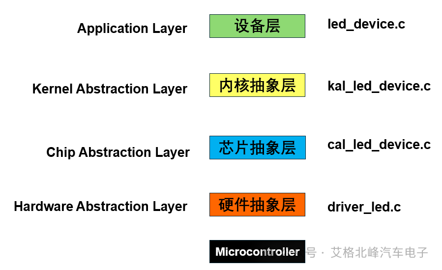
2. Device Layer
In the device layer, there is a structure for the LED device, which lists all supported LED devices, supporting white, blue, and green lights, as well as LED initialization and control, as shown in the figure below:
static LEDDevice g_tLEDDevices[] = { {LED_WHITE, 0, LEDDeviceInit, LEDDeviceControl}, {LED_BLUE, 0, LEDDeviceInit, LEDDeviceControl}, {LED_GREEN, 0, LEDDeviceInit, LEDDeviceControl},};Below are the functions of the device layer: LEDDeviceInit(), LEDDeviceControl(), GetLEDDevice().
/********************************************************************** * Function Name: LEDDeviceInit * Function Description: LED initialization function for the device layer * Input Parameter: ptLEDDevice - which LED device * Output Parameter: None * Return Value: 0-success ***********************************************************************/static int LEDDeviceInit(struct LEDDevice *ptLEDDevice){ return KAL_LEDDeviceInit(ptLEDDevice);}/********************************************************************** * Function Name: LEDDeviceControl * Function Description: LED control function for the device layer * Input Parameter: ptLEDDevice - which LED device * Input Parameter: iStatus, 1-on, 0-off * Output Parameter: None * Return Value: 0-success ***********************************************************************/static int LEDDeviceControl(struct LEDDevice *ptLEDDevice, int iStatus){ return KAL_LEDDeviceControl(ptLEDDevice, iStatus);}/********************************************************************** * Function Name: GetLEDDevice * Function Description: Get LED device * Input Parameter: which - which LED device * Value options: LED_WHITE, LED_BLUE or LED_GREEN * Output Parameter: None * Return Value: Success - LEDDevice pointer, Failure - NULL ***********************************************************************/PLEDDevice GetLEDDevice(int which){ if (which >= LED_WHITE && which <= LED_GREEN) return &g_tLEDDevices[which]; else return NULL;}3. Kernel Abstraction Layer
In the kernel abstraction layer, our program can set macros at compile time to choose the applicable operating system, currently divided into bare metal, FreeRTOS, and RT-Thread.

Below are the functions of the device layer: KAL_OLEDDeviceInit(), OLEDDeviceFlush(), GetLEDDevice().
/********************************************************************** * Function Name: KAL_LEDDeviceInit * Function Description: LED initialization function for the kernel abstraction layer, please modify this function when the kernel is different * Input Parameter: ptLEDDevice - which LED device * Output Parameter: None * Return Value: 0-success ***********************************************************************/int KAL_LEDDeviceInit(struct LEDDevice *ptLEDDevice){ /* For bare metal */ #if defined (CONFIG_NOOS) return CAL_LEDDeviceInit(ptLEDDevice); /* For RT-Thread */ #elif defined (CONFIG_FREERTOS) return FreeRTOS_LEDDeviceInit(ptLEDDevice); /* For Linux */ #elif defined (CONFIG_RTTHREAD) return RTThread_LEDDeviceInit(ptLEDDevice);}/********************************************************************** * Function Name: KAL_LEDDeviceControl * Function Description: LED control function for the kernel abstraction layer, please modify this function when the kernel is different * Input Parameter: ptLEDDevice - which LED device * Input Parameter: iStatus, 1-on, 0-off * Output Parameter: None * Return Value: 0-success ***********************************************************************/int KAL_LEDDeviceControl(struct LEDDevice *ptLEDDevice, int iStatus){ /* For bare metal */ #if defined (CONFIG_NOOS) return CAL_LEDDeviceControl(ptLEDDevice, iStatus); /* For RT-Thread */ #elif defined (CONFIG_FREERTOS) return FreeRTOS_LEDDeviceControl(ptLEDDevice, iStatus); /* For Linux */ #elif defined (CONFIG_RTTHREAD) return RTThread_LEDDeviceControl(ptLEDDevice, iStatus);}4. Chip Abstraction Layer
Below is the chip abstraction layer, here we only show the bare metal program.
/********************************************************************** * Function Name: CAL_LEDDeviceInit * Function Description: LED initialization function for the chip abstraction layer, please modify this function when the chip function is different * Input Parameter: ptLEDDevice - which LED device * Output Parameter: None * Return Value: 0-success ***********************************************************************/int CAL_LEDDeviceInit(struct LEDDevice *ptLEDDevice){ /* For hal */ /* The pins have already been initialized in MX_GPIO_Init */ return 0;}/********************************************************************** * Function Name: CAL_LEDDeviceControl * Function Description: LED control function for the chip abstraction layer, please modify this function when the chip function is different * Input Parameter: ptLEDDevice - which LED device * Input Parameter: iStatus, 1-on, 0-off * Output Parameter: None * Return Value: 0-success ***********************************************************************/int CAL_LEDDeviceControl(struct LEDDevice *ptLEDDevice, int iStatus){ /* For hal */ return HAL_LEDDeviceControl(ptLEDDevice, iStatus);}5. Hardware Abstraction Layer
The hardware abstraction layer uses a switch case function to continuously switch the LED’s on/off state based on the LED structure type and control state passed from the upper layer.
/* * Function Name: int HAL_LEDDeviceControl(struct LEDDevice *ptLEDDevice, int iStatus) * Input Parameter: ptLEDDevice - which LED * Input Parameter: iStatus - LED state, 1-on, 0-off * Output Parameter: None * Return Value: 0-success, -1: failure */int HAL_LEDDeviceControl(struct LEDDevice *ptLEDDevice, int iStatus){ if (!ptLEDDevice) return -1; switch (ptLEDDevice->which) { case LED_WHITE: { HAL_GPIO_WritePin(WHITE_GPIO_Port, WHITE_Pin, !iStatus); break; } case LED_BLUE: { HAL_GPIO_WritePin(BLUE_GPIO_Port, BLUE_Pin, !iStatus); break; } case LED_GREEN: { HAL_GPIO_WritePin(GREEN_GPIO_Port, GREEN_Pin, !iStatus); break; } default: return -1; } return 0;}6. Test Code
Below is the test code, which makes each LED light up and turn off continuously every 500ms.
/********************************************************************** * Function Name: led_test * Function Description: Unit test function for LED device in the device system * Input Parameter: None * Output Parameter: None * Return Value: None ***********************************************************************/void led_test(void){ PLEDDevice p1 = GetLEDDevice(LED_WHITE); PLEDDevice p2 = GetLEDDevice(LED_BLUE); PLEDDevice p3 = GetLEDDevice(LED_GREEN); p1->Init(p1); p2->Init(p2); p3->Init(p3); while (1) { p1->Control(p1, 1); p2->Control(p2, 1); p3->Control(p3, 1); KAL_Delay(500); p1->Control(p1, 0); p2->Control(p2, 0); p3->Control(p3, 0); KAL_Delay(500); }}Call the led_test() function in the main.c function:
int main(void){ HAL_Init(); // Initialize HAL library, set system-related interrupts and clock. SystemClock_Config(); // Configure system clock to make the chip work at the target frequency. MX_GPIO_Init(); // Initialize GPIO peripherals to prepare for input and output. MX_USART1_UART_Init(); // Initialize USART1 for debugging information output. MX_USART3_UART_Init(); // Initialize USART3 for serial communication. ring_buffer_init(&test_buffer); // Initialize circular Buffer. EnableDebugIRQ(); printf("Hello World!\r\n"); // Print debugging information to confirm system startup success. while (1) { //input_test(); // Enter input test loop, process input events. led_test(); // Enter LED test loop }}7. Practical Demonstration
Next, download the program into the development board, and the effect is shown below:
STM32 IoT Smart Home (1) Scheme Design – STM32 + ESP8266 + TCP/UDP/MQTT
STM32 IoT Smart Home (2) – Development Environment and Project Setup (STM32CubeMX)
STM32 IoT Smart Home (3) Input Subsystem
STM32 IoT Smart Home (4) Device Subsystem Layered Framework
STM32 Customer BootLoader Refresh Project (1) STM32CubeMX UART Communication Project Setup
STM32 Customer BootLoader Refresh Project (2) Scheme Introduction
STM32 Customer BootLoader Refresh Project (3) Program Framework Setup
STM32 BootLoader Refresh Project (4) Communication Protocol
······
STM32 BootLoader Refresh Project (11) Flash Write Operation – Command 0x57
STM32 BootLoader Refresh Project (13) Python Host Introduction
STM32 BootLoader Refresh Project (14) All Source Code Acquisition