Many beginners, after learning the basic instructions, still do not know where to start when faced with a real project. Today, we will outline a standardized process for a complete PLC project from scratch. Mastering this process will allow you to work methodically like an experienced engineer.
Step 1: Deeply Understand Control Requirements (Sharpening the Axe Does Not Hinder the Work) This is the foundation of all work. You must communicate repeatedly with mechanical engineers, electrical engineers, or clients to thoroughly understand:
-
What actuators does the equipment have? (Motors, cylinders, valves, indicator lights, etc.)
-
How does each actuator need to operate? (Momentary, continuous operation, forward and reverse?)
-
What detection elements does the equipment have? (Buttons, switches, sensors, encoders, etc.)
-
What is the process flow of the entire equipment? Are there any safety interlock requirements?
-
It is best to obtain mechanical timing diagrams or process flow diagrams, which are golden references for programming.
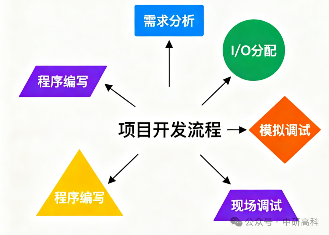
Step 2: Hardware Selection and Electrical Diagram Design Based on the requirements, select the appropriate PLC model (considering I/O points, memory, functions, etc.) and design the electrical schematic and wiring diagram. This step is usually completed by senior electrical engineers, but programmers must be able to understand it.
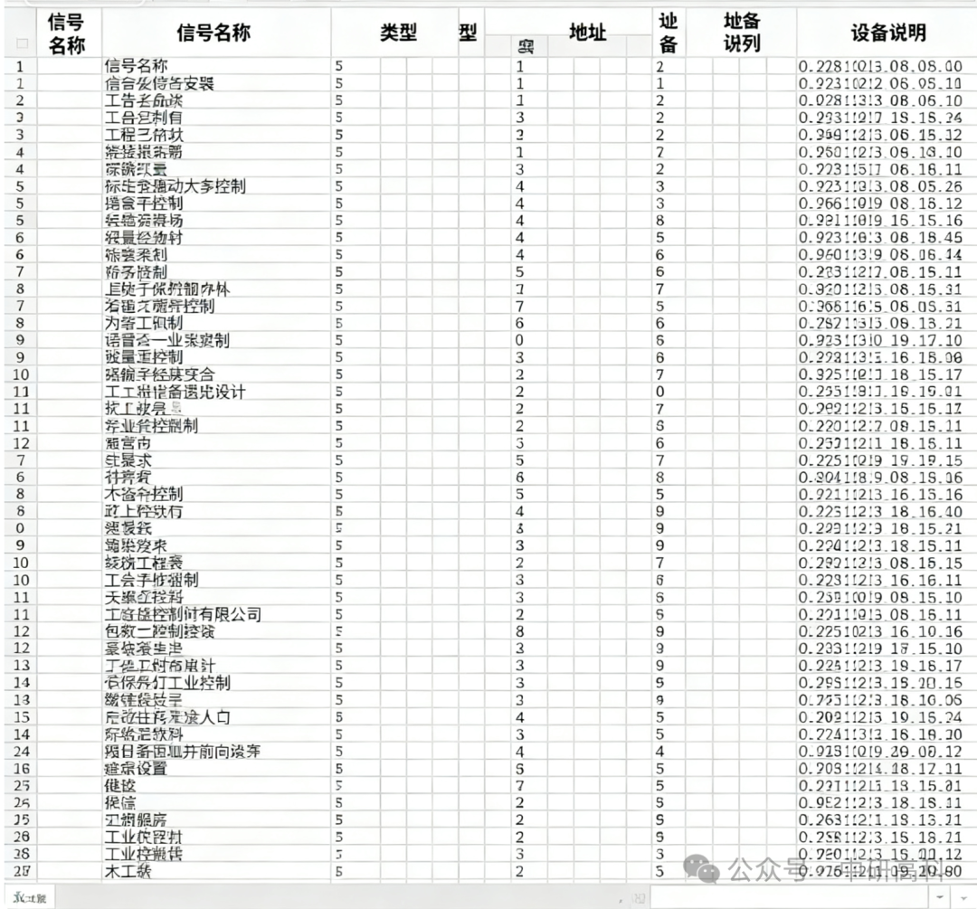
Step 3: Critical I/O Allocation This is the bridge connecting hardware and software. You need to create an I/O allocation table that corresponds the physical input and output points with the soft element addresses in the program.
-
Input Points: For example:
<span>I0.0</span>-><span>Start Button</span>;<span>I0.1</span>-><span>Stop Button</span>;<span>I1.0</span>-><span>Cylinder Front Limit Sensor</span> -
Output Points: For example:
<span>Q0.0</span>-><span>Main Contactor</span>;<span>Q0.1</span>-><span>Red Light</span>;<span>Q0.2</span>-><span>Green Light</span>This approach makes the program clear, and during later maintenance, anyone can understand which actual device corresponds to the address.
Step 4: Program Writing and Structuring Do not dive straight into writing a large block of code. Excellent programmers will first conduct program structure planning:
-
Main Program (OB1): Calls various subprograms.
-
Subprograms/Function Blocks (FC/FB): Modularize functions. For example:
<span>Manual Mode FC</span>,<span>Automatic Mode FC</span>,<span>Alarm Handling FC</span>,<span>Cylinder Control FB</span>, etc. -
Use structured programming to make the program logic clear, easy to read, and debug.
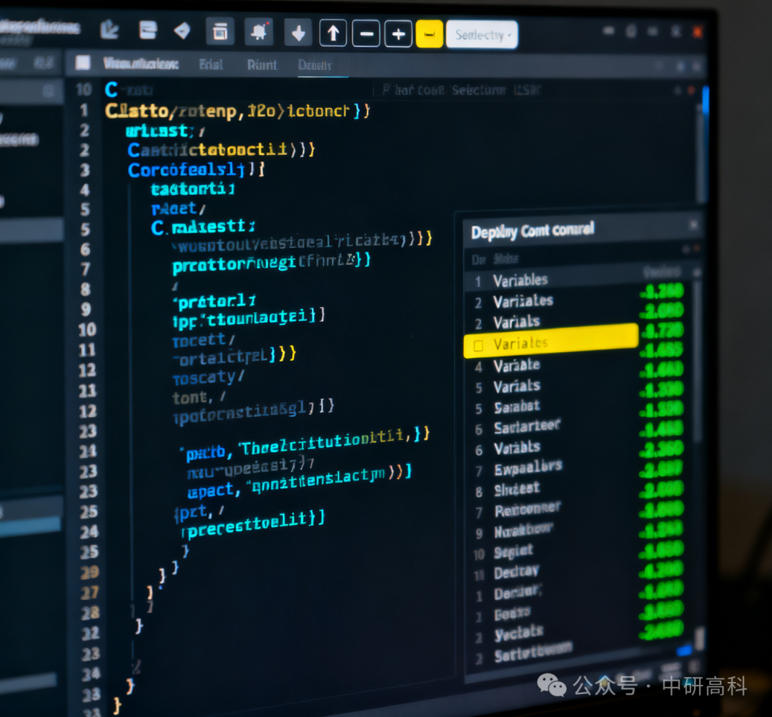
Step 5: Simulation Debugging (Software Simulation) Before downloading the program to the real PLC, be sure to use the simulation function of the programming software for testing.
-
In the simulator, you can force changes to the on/off state of input points, simulating the actions of field buttons and sensors.
-
Observe whether the output points operate as expected and whether the program logic is correct.
-
This step can identify most logical errors in the program, avoiding risks during field operations and greatly improving efficiency.
Step 6: On-Site Online Debugging After the program simulation is confirmed to be correct, connect the real PLC and equipment for final debugging.
-
Download Program: Download the program to the PLC.
-
No-load Debugging: Temporarily disconnect the load from the output points (e.g., motor power), only observe whether the output point indicator lights operate correctly, ensuring the logic is flawless.
-
Load Debugging: Connect the load and conduct step-by-step testing in single-point, manual, and automatic modes.
-
Optimization and Improvement: Based on the actual operating conditions of the equipment, fine-tune timer times, action sequences, etc., to achieve optimal operation of the equipment.
By following this standardized process, you can avoid detours in your work and become a professional and efficient engineer.