Functions of PLC Control Cabinets
The PLC comprehensive control cabinet has protective functions such as overload, short circuit, and phase loss protection. It features a compact structure, stable operation, and complete functionality. It can be combined according to the actual control scale, allowing for both single cabinet automatic control and multiple cabinets to form a distributed control system (DSC) through industrial Ethernet or fieldbus networks. The PLC control cabinet can adapt to various sizes of industrial automation control scenarios.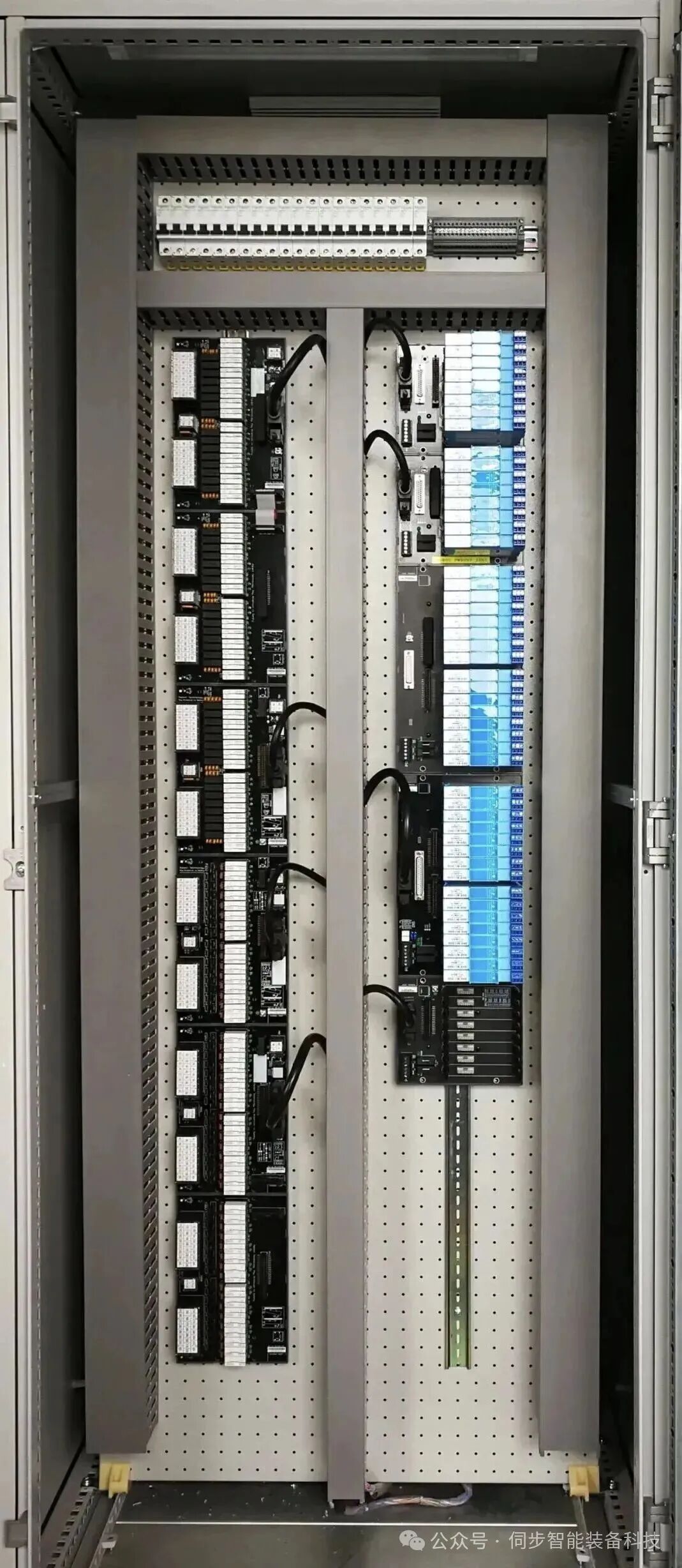
Components of PLC Control Cabinets
1. Circuit Breaker: A main circuit breaker, which controls the power supply for the entire cabinet. This is something that every cabinet must have. 2. PLC: This should be selected based on project requirements. For example, if the project is small, a compact PLC may suffice, but for larger projects, modular or card-based PLCs may be necessary, and redundancy (i.e., two sets operating alternately) may also be required. 3. 24VDC Power Supply: A 24VDC switching power supply; most PLCs come with a built-in 24VDC power supply, and whether this switching power supply is needed depends on actual requirements. 4. Relays: Generally, PLCs can directly send commands to the control circuit, but they may also go through relays. For example, if the output of your PLC is 24VDC, but your control circuit requires 220VAC, you must add a relay at the PLC output. When the command is issued, the relay activates, allowing the control circuit to connect to the relay’s normally open or normally closed points. The use of relays depends on the situation.5. Terminal Blocks: These are essential components in every cabinet and can be configured based on the number of signals. If it is just a simple PLC control cabinet, these components are generally required. If your control cabinet needs additional components, you may need to add more circuit breakers, for example, if you need to power certain field instruments or small control boxes, or if you need to connect the PLC to a host computer, you may need to add switches, depending on the situation.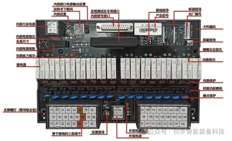 The PLC control cabinet can achieve automation of equipment and process control, realizing perfect network functionality, stable performance, expandability, and strong anti-interference characteristics, making it the core and soul of modern industry. It can be custom-designed according to user requirements for PLC control cabinets, frequency conversion cabinets, etc., to meet user needs, and can be paired with human-machine interface touch screens for easy operation. The equipment can also communicate with DCS host computers using protocols such as Modbus and Profibus for data transmission; control and monitoring can be achieved through industrial computers and Ethernet.
Operating Conditions for PLC Control Cabinets
Power Supply: DC 24V, two-phase AC 220V, (-10%, +15%), 50HZ;Protection Level: IP41 or IP20; Environmental Conditions: Ambient temperature between 0℃-55℃, preventing direct sunlight; relative humidity should be less than 85% (no condensation). Keep away from strong vibration sources, preventing frequent or continuous vibrations at frequencies of 10-55HZ. Avoid corrosive and flammable gases.
Basic Structure of PLC Control Cabinets
A Programmable Logic Controller (PLC) is essentially a computer specifically designed for industrial control, with a hardware structure similar to that of a microcomputer, consisting of:1. Power Supply The power supply of the PLC plays a crucial role in the entire system. Without a good and reliable power supply system, it cannot operate normally. Therefore, PLC manufacturers pay great attention to the design and manufacture of power supplies. Generally, if the AC voltage fluctuation is within +10% (+15%), the PLC can be directly connected to the AC power grid without additional measures.2. Central Processing Unit (CPU)The CPU is the control center of the PLC. It receives and stores the user program and data input from the programmer according to the functions assigned by the PLC system program; checks the status of the power supply, memory, I/O, and watchdog timer, and can diagnose syntax errors in the user program. When the PLC is put into operation, it first scans the status and data of all input devices in the field and stores them in the I/O image area, then reads the user program from the user program memory line by line, interprets the commands, and executes the logical or arithmetic operations as specified, sending the results to the I/O image area or data registers. After all user programs are executed, the output states in the I/O image area or the data in the output registers are sent to the corresponding output devices, and this cycle continues until stopped.To further enhance the reliability of the PLC, recent large PLCs have adopted dual CPU configurations for redundancy or a triple CPU voting system. This way, even if one CPU fails, the entire system can continue to operate normally.3. MemoryThe memory that stores the system software is called system program memory.The memory that stores application software is called user program memory.4. Input/Output Interface Circuits1. The field input interface circuit consists of optocoupler circuits and the microcomputer’s input interface circuit, serving as the input channel for the PLC to interface with field control.2. The field output interface circuit integrates output data registers, gating circuits, and interrupt request circuits, allowing the PLC to output corresponding control signals to field actuators through the field output interface circuit.5. Function ModulesSuch as counting, positioning, and other function modules.6. Communication ModulesOperating Principle:When the PLC is put into operation, its working process generally consists of three stages: input sampling, user program execution, and output refreshing. Completing these three stages is called a scan cycle. During the entire operation, the PLC’s CPU repeatedly executes these three stages at a certain scan speed.1. Input Sampling StageIn the input sampling stage, the PLC sequentially reads all input statuses and data in a scanning manner and stores them in the corresponding units of the I/O image area. After input sampling is complete, it transitions to the user program execution and output refreshing stages. In these two stages, even if the input status and data change, the statuses and data in the corresponding units of the I/O image area do not change. Therefore, if the input is a pulse signal, the width of that pulse signal must be greater than one scan cycle to ensure that the input can be read under any circumstances.2. User Program Execution StageIn the user program execution stage, the PLC always scans the user program (ladder diagram) in a top-down order. When scanning each ladder diagram, it first scans the control circuits formed by the contacts on the left side of the ladder diagram and performs logical operations on the control circuits formed by the contacts in a left-to-right, top-to-bottom order. Then, based on the results of the logical operations, it refreshes the status of the corresponding bits in the system RAM storage area for that logic coil; or refreshes the status of the corresponding bits in the I/O image area for that output coil; or determines whether to execute the special function instructions specified by the ladder diagram.During the execution of the user program, only the input points in the I/O image area do not change, while other output points and soft devices in the I/O image area or system RAM storage area may change. Moreover, the results of the program execution for the ladder diagrams above will affect those below that use these coils or data; conversely, the logic coils’ statuses or data refreshed by the ladder diagrams below will only take effect in the next scan cycle for those above.If immediate I/O instructions are used during program execution, they can directly access I/O points. That is, when using I/O instructions, the values in the input process image registers will not be updated, and the program directly retrieves values from the I/O module, while the output process image registers will be immediately updated, which differs from immediate input. 3. Output Refreshing StageAfter the user program scanning is complete, the PLC enters the output refreshing stage. During this period, the CPU refreshes all output latch circuits according to the corresponding statuses and data in the I/O image area, and then drives the corresponding external devices through the output circuits. This is when the PLC’s true output occurs.Functional Characteristics:The PLC has the following distinct characteristics.1. Flexible system composition, easy expansion, with digital control as its specialty; it can also perform continuous process PID loop control; and can form complex control systems with upper-level devices, such as DDC and DCS, achieving comprehensive automation of production processes.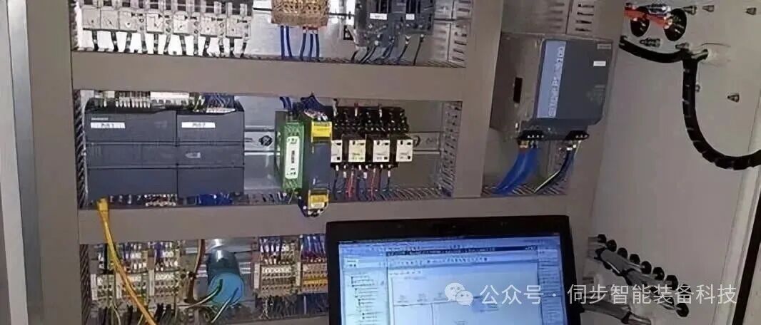 2. Easy to use, simple programming, using clear ladder diagrams, logic diagrams, or statement tables as programming languages, without requiring computer knowledge, thus shortening the system development cycle and facilitating on-site debugging. Additionally, programs can be modified online, changing control schemes without disassembling hardware.3. Can adapt to various harsh operating environments, with strong anti-interference capabilities and high reliability, far exceeding other types of models.
Source: iPEBG Equipment Health Management Department. For learning and communication purposes only, copyright belongs to the original author. If there is any infringement, please contact for deletion!
 Scan the QR code to follow me!