NEWS
Click the blue text to follow us
NEWS TODAY
The active suspension system mainly consists of components such as sensors, actuators, and controllers. Among them, sensors are used to perceive road conditions and driver demands, enabling real-time monitoring of suspension performance, thereby improving vehicle handling, comfort, and safety.
In the sensor design process, to ensure reliable data transmission, a universal interface is required. PSI5 is a communication protocol developed for automotive sensors, featuring an anti-interference interface and a communication rate compatible with sensors, effectively ensuring data transmission.
01 Overview of PSI5
The PSI5 protocol (Peripheral Sensor Interface) is a widely used bidirectional digital communication protocol in the automotive electronics field, primarily for data transmission between sensors and electronic control units (ECUs). Its advantages include low power consumption, high anti-interference capability, and low cost, making it particularly suitable for scenarios requiring high real-time performance and reliability, such as airbags and pressure sensors.
1. Physical Layer
PSI5 uses twisted pair cables to provide power and data transmission between the ECU and the sensor. The ECU supplies regulated voltage to the sensor through the PSI5 transceiver and reads the data transmitted by it. Sensor data is transmitted to the ECU in the form of current using Manchester encoding format.
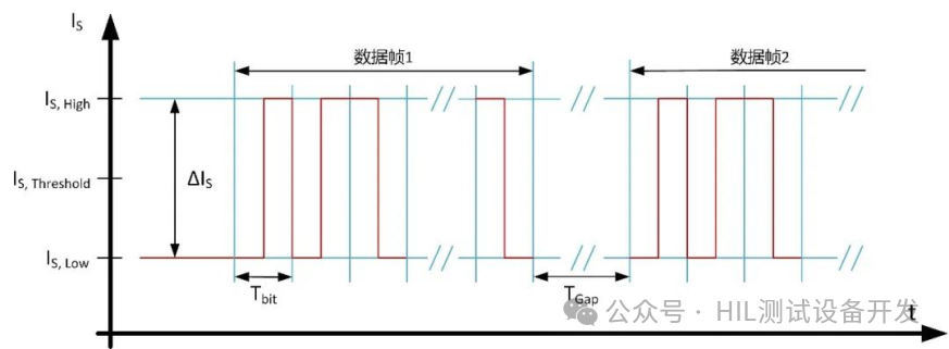
Figure 1 Encoding and frame timing parameters for communication from sensor to ECU
The connection topology between the sensor and ECU mainly includes: asynchronous connection mode (PSI5-A), synchronous parallel bus mode (PSI5-P), synchronous universal bus mode (PSI5-U), and synchronous daisy chain bus mode (PSI5-D).
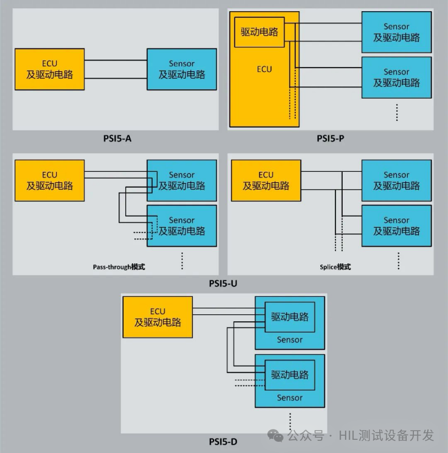
Figure 2 Simplified diagram of PSI5 connection topology
2. Data Link Layer
The PSI5 data transmission format consists of: 2 start bits, 10-28 data bits, and 1 parity bit or CRC check bit.
The amplitude of the induced voltage signal is related to the rotation angle of the rotor, expressed as:
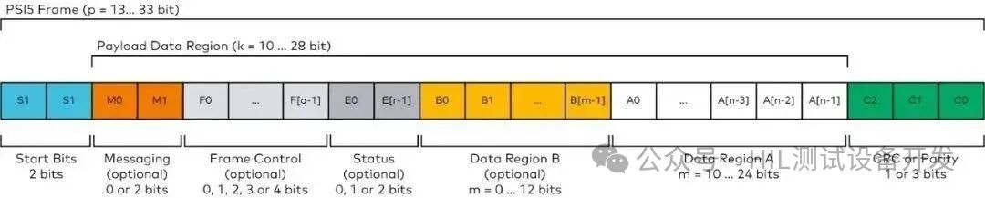
Figure 3 PSI5 data frame transmission format
In synchronous mode, the ECU periodically sends a high-level voltage signal as a synchronization pulse while supplying power to the sensor. Each sensor, upon detecting the synchronization pulse, sends its current signal to transmit data according to the pre-configured time slot (TimeSlot).
When the serial message (SerialMessage) channel bit is set to 2 bits in length, the serial message will be transmitted through 18 consecutive frames, generally used for data with low update cycle requirements.
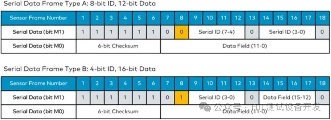
Figure 4 Serial message data frame format
3. Application Layer
Data range: For the 10-bit data transmitted in data domain A, the PSI5 specification divides it into three parts:
-
-480 to +480 (0x1E0-0x220) represents the actual output signal value of the sensor;
-
-512 to -481 (0x200-0x20F) represents the block (Block) ID and data, used for transmitting initialization data;
-
+481 to +511 (0x1E1-0x1FF) represents status and error messages.
For the lower part of data greater than 10 bits in data domain A and data domain B, it is not affected by this data range division.
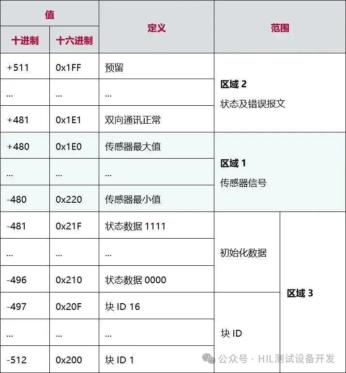
Figure 5 Definition of the 10-bit data range in data domain A
Sensor initialization:
After each power-up or reset, the initialization identification information must be sent before transmitting any valid sensor data.
Initialization generally consists of three stages:
-
Stage 1: Sensor startup, no data sent;
-
Stage 2: Send ID + initialization data information, while the sensor performs self-check;
-
Stage 3: Send the sensor self-check results. After initialization is complete, normal data and sensor self-check status information can be transmitted.
02 PSI5 Sensor Simulation
In the development of suspension systems, verifying the communication logic between the sensor and ECU in advance is key to shortening the cycle.
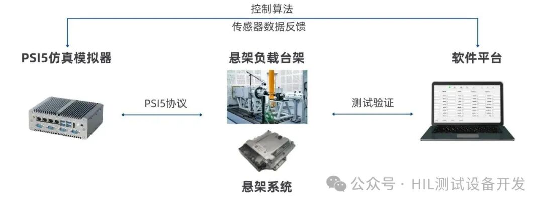
Figure 6 Closed-loop testing architecture for PSI5 sensor simulation and analysis
-
Channel Multiplexing Technology
-
A single physical channel can virtually simulate 6 independent sensors, allowing a 128-channel system to simulate a super-large-scale network of 768 nodes.
-
Dynamic Behavior Modeling
-
Built-in various fault models such as temperature drift, signal attenuation, and noise injection, supporting Monte Carlo random simulation.
-
Precise Timing Control
-
Using FPGA hardware timestamp mechanism to achieve signal synchronization at the level of 10ns, meeting ASIL D functional safety verification requirements.
03 PSI5 Signal Analysis and Debugging
Physical Layer Signal Decoding
Real-time display of voltage waveforms, pulse width modulation (PWM) characteristics, and signal integrity metrics.
Protocol Layer Data Analysis
Automatically extract structured information such as sensor ID, measurement values, and status flags.
Application Layer Semantic Restoration
Supports user-defined scripts to convert raw data into engineering units (e.g., kPa, °C).
04 Core Applications of PSI5 in Automotive Suspension Systems
Simulation Testing
Hardware-in-the-loop (HIL) simulation: Simulate sensor signals and replicate real vehicle road conditions (e.g., bumpy road acceleration waveforms) to verify ECU communication logic in advance.
Fault Injection and Fault Tolerance Testing
Can simulate wiring short circuits, disconnections, and other faults to test the ECU’s ability to handle abnormal signals.
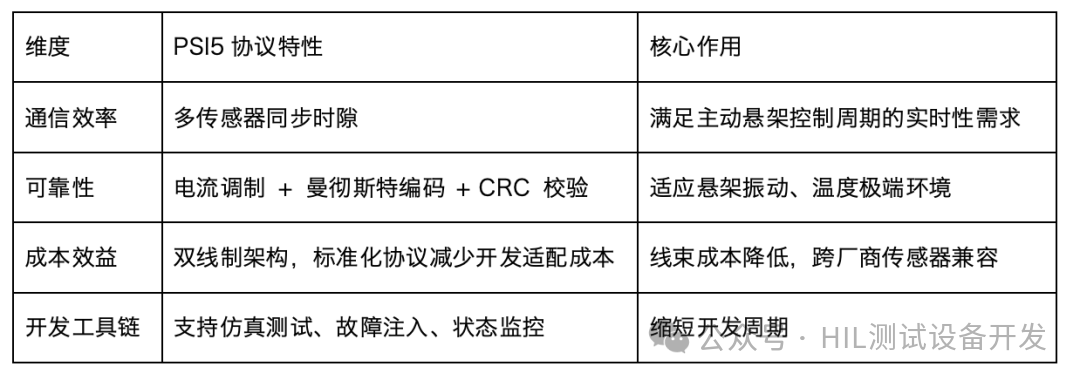
Figure 7 Core advantages of the PSI5 protocol
05 Conclusion
With its efficient communication mechanism and high reliability, the PSI5 protocol has become a core technology for active suspension systems. Its simulation and analysis technology supports full-process laboratory validation, accelerating the collaborative development of sensors and ECUs.
As automotive intelligence develops, PSI5 will further empower the deep integration of suspension systems and autonomous driving, promoting comprehensive improvements in vehicle handling, comfort, and safety.
END

Scan the code to follow us