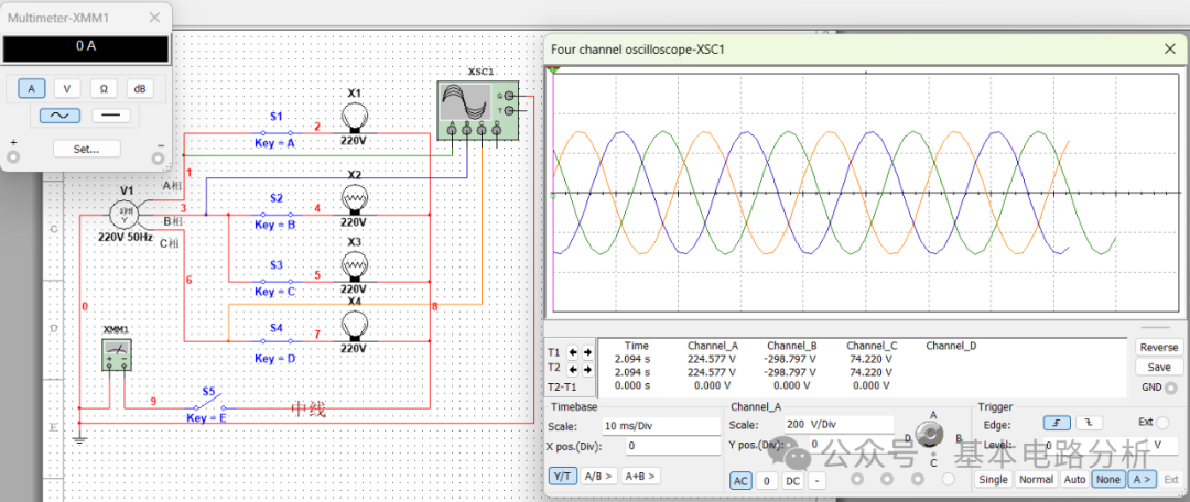
Place a Y-connected three-phase power supply V1 in the Multisim workspace (set its effective value to 220V, frequency 50Hz), and place 5 single-pole single-throw switches S1, S2, S3, S4, S5 (these can be controlled by left-clicking the mouse to open/close the switches, or set to be controlled by the keyboard characters A, B, C, D, E), place 4 loads (i.e., rated voltage 220V yellow light bulbs X1, X2, X3, X4), then place 1 4-channel oscilloscope XSC1, 1 multimeter XMM1, and finally place 1 ground symbol.
Connect the left port of V1 to the “ground symbol” (i.e., the Y connection of the symmetrical three-phase power supply is grounded), load X1 is connected to phase A power supply through switch S1, X2 is connected to phase B power supply through switch S2, X3 is also connected to phase B power supply through switch S3, X4 is connected to phase C power supply through switch S4, and the three-phase loads are also connected in a Y configuration, with the common terminal of the three-phase load connected to the common terminal of the three-phase power supply through switch S5 (forming a three-phase four-wire system).
(1) Close switches S1, S2, S3, S4, and it is evident that the three-phase load is unbalanced ( phase A connects 1 bulb, phase B connects 2 parallel bulbs, phase C connects 1 bulb), close S5 as well, introducing the neutral line. Observe the A channel of the oscilloscope for phase A power supply (green), B channel for phase B power supply (blue), C channel for phase C power supply (yellow). Use the multimeter to measure the current between the common terminal of the power supply and the common terminal of the load. Start the simulation and observe that each phase load ( 4 bulbs) is functioning normally. The oscilloscope waveform is that of a symmetrical three-phase power supply, and the multimeter reading is 45.474mA, indicating that the neutral line current is not 0. The simulation results are shown in the figure below.
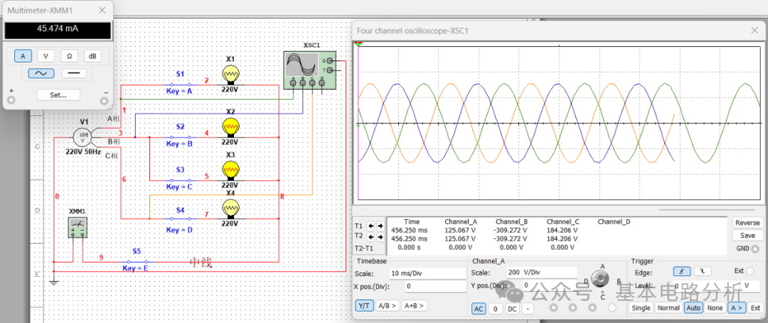
(2)) Close switches S1, S2, S4 and open switch S3, so that the three-phase loads connected to each phase power supply are symmetrical. Start the simulation, and it can be observed that regardless of whether S5 is open or closed, X1, X2, X4 all light up normally, the oscilloscope waveform is normal, and the multimeter reading is 0A. This means that when the load is symmetrical, whether the neutral line is connected or not does not affect the load’s operating state. (Simulation results are shown in the figure below)
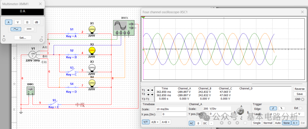
(3)) Close switches S1, S2, S3, S4 and open switch S5, so that the loads connected to each phase power supply are unbalanced, and the neutral line is also disconnected. Start the simulation and observe that none of the bulbs can light up. (Simulation results are shown in the figure below)
Readers can change the connection of the loads themselves to observe the operating state of the three-phase circuit and understand the role of the neutral line.