Click on the above Electrical Engineering Learning to follow and star it.
A professional self-media in the field of electrical engineering, don’t miss it.

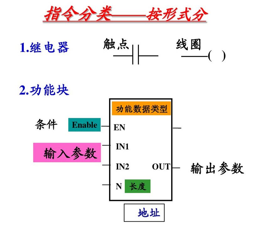
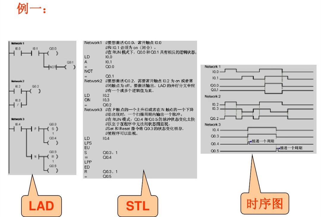
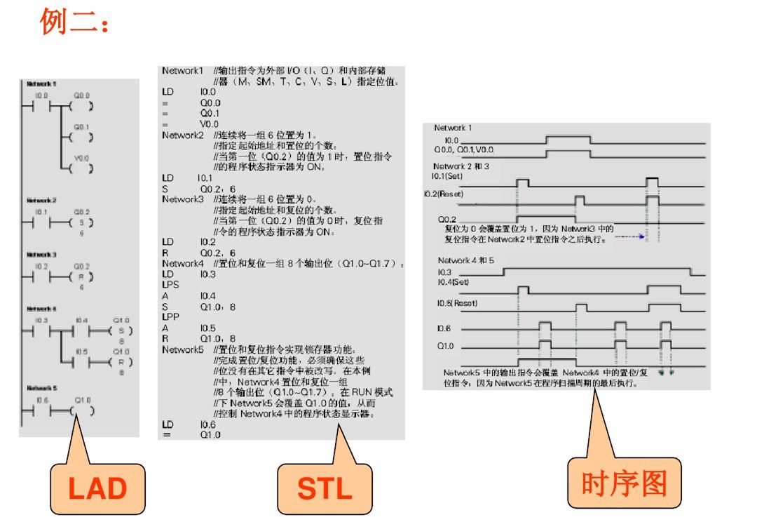
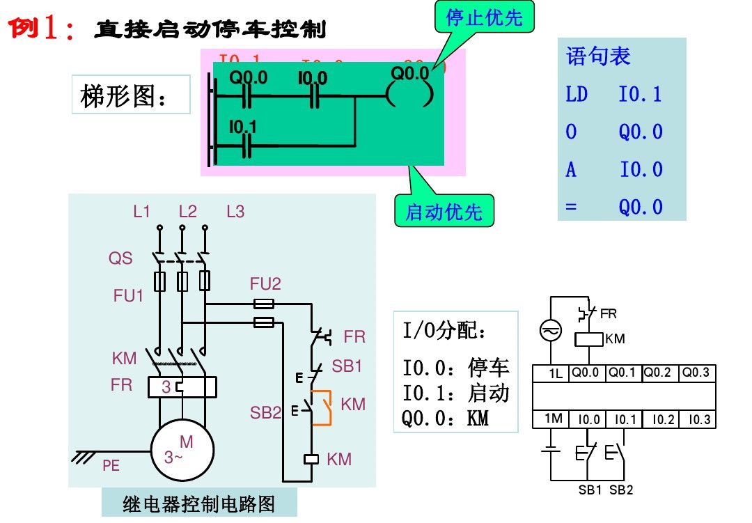
1. Bit Logic Instructions
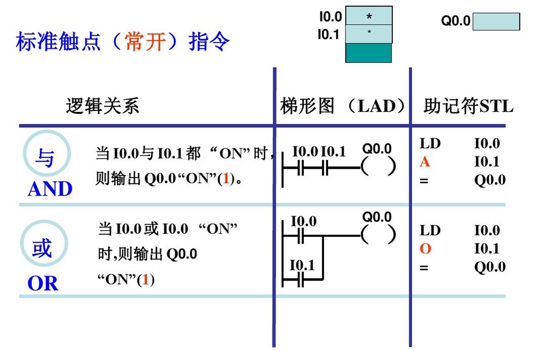
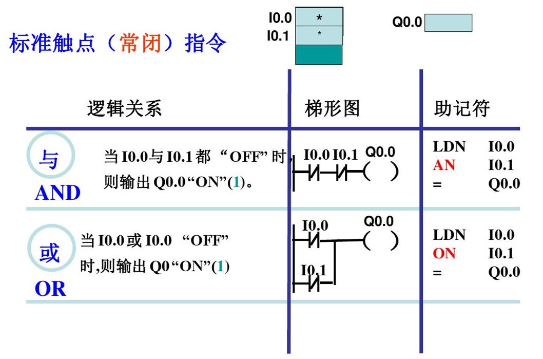
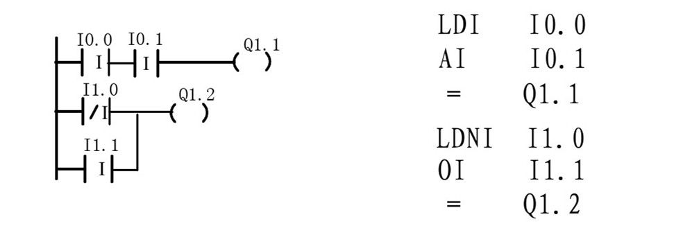
(1) Contact and Coil Instructions
Programming principles of PLC ladder diagram language:
1. The ladder diagram consists of multiple rungs, each coil can form a rung, and each rung has multiple branches, with each rung representing a logical equation;
2. The relays, contacts, and coils in the ladder diagram are not physical; they are bits in the PLC memory (1=ON; 0=OFF); normally open/closed contacts can be referenced infinitely, while coil outputs can only be referenced once;
3. The flow in the ladder diagram is not physical current but “conceptual current”, which can only flow from left to right;
4. The calculations of the user program are based on the contents of the PLC’s input/output image registers, and the results of logical operations can be immediately used by subsequent programs;
5. The internal relays of the PLC cannot be used for control; they can only store intermediate states of logical control;
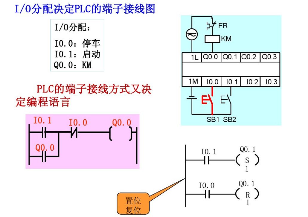
6. Output coils cannot directly drive field actuators; they must drive through power devices on the I/O module.
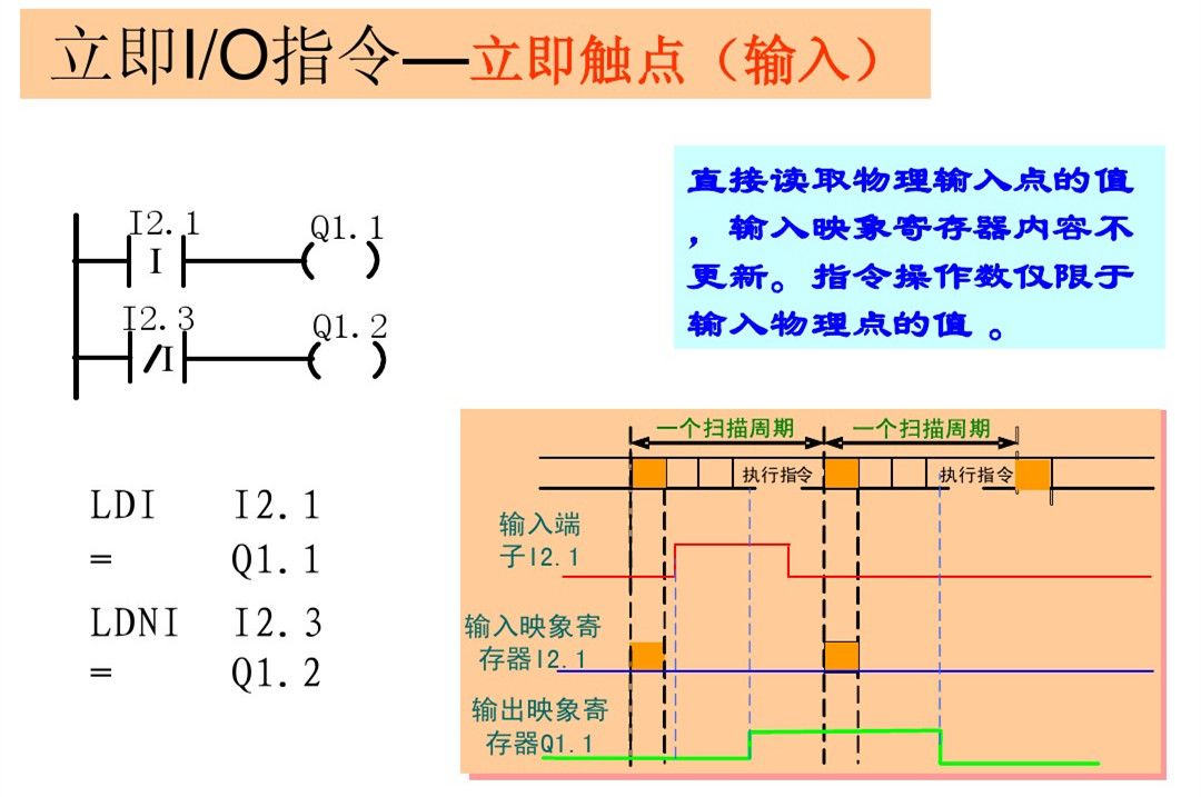
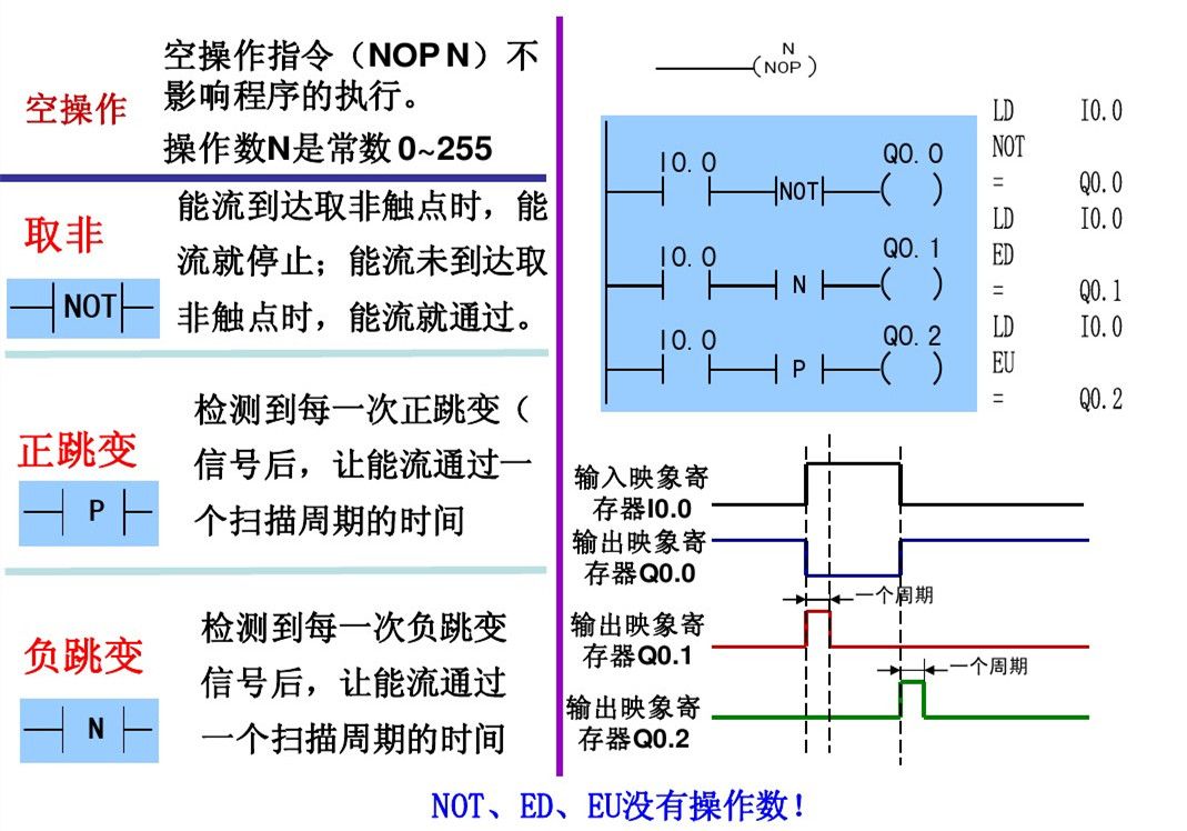
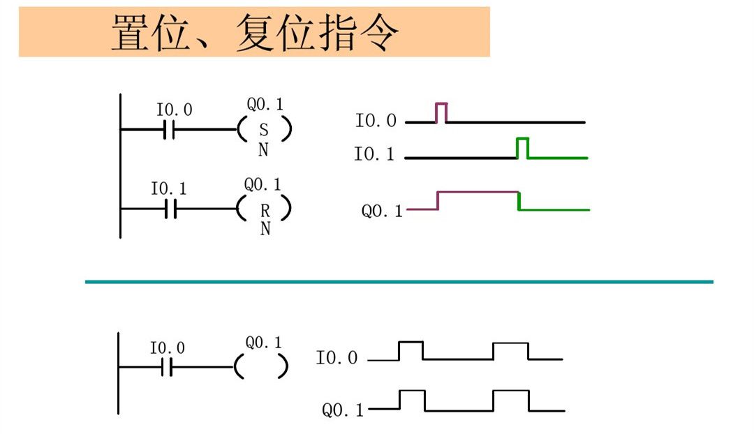
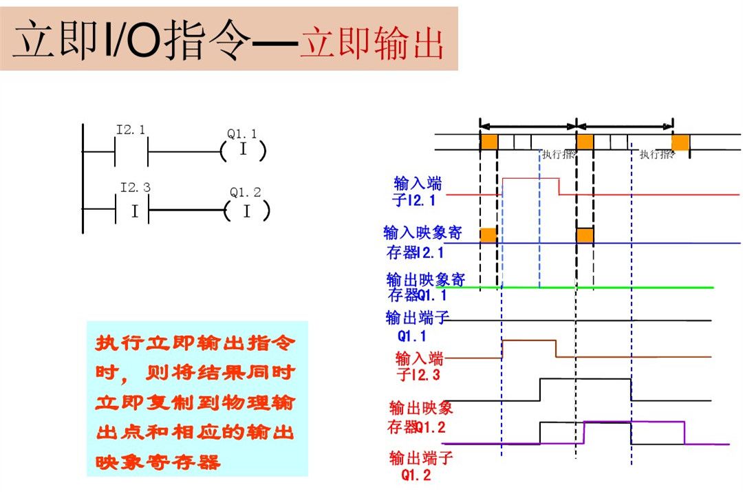
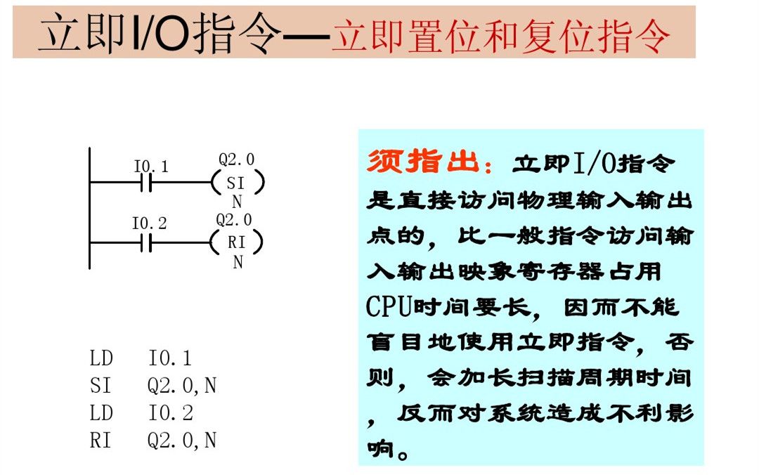
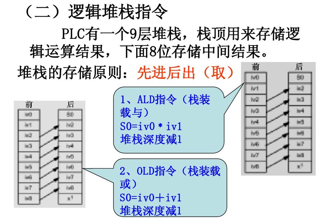
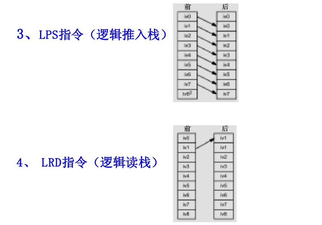
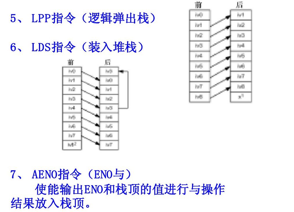
The basic logic instructions focus on bit logic operations. In bit logic instructions, unless otherwise specified, the valid operand areas are: I, Q, M, SM, T, C, V, S, L, and the data type is BOOL. Contact and coil instructions are further divided into: standard instructions, immediate instructions, negation instructions, and positive (negative) edge instructions.

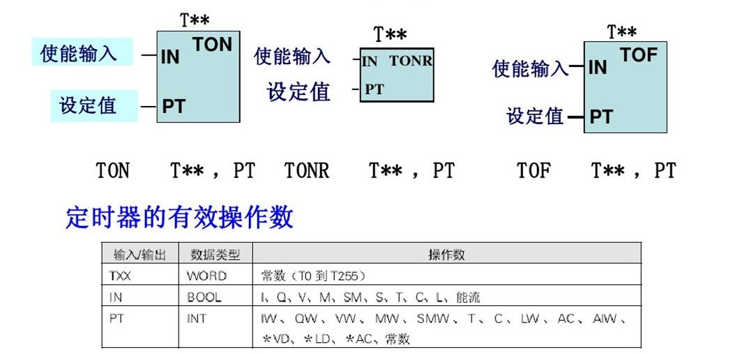
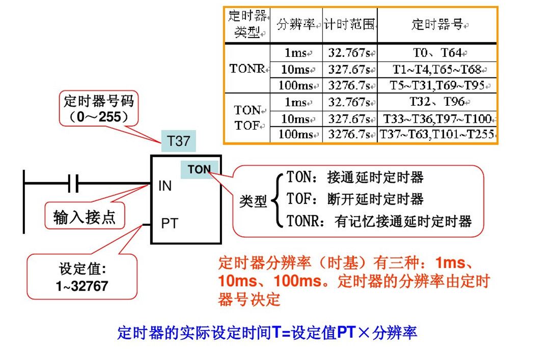
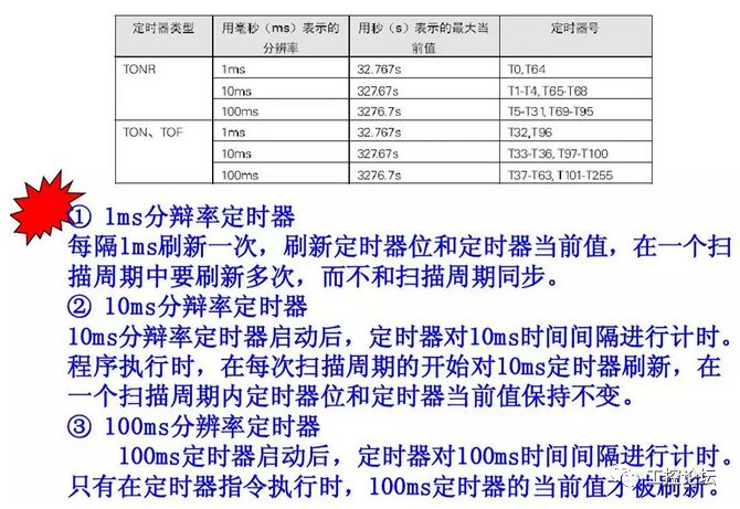
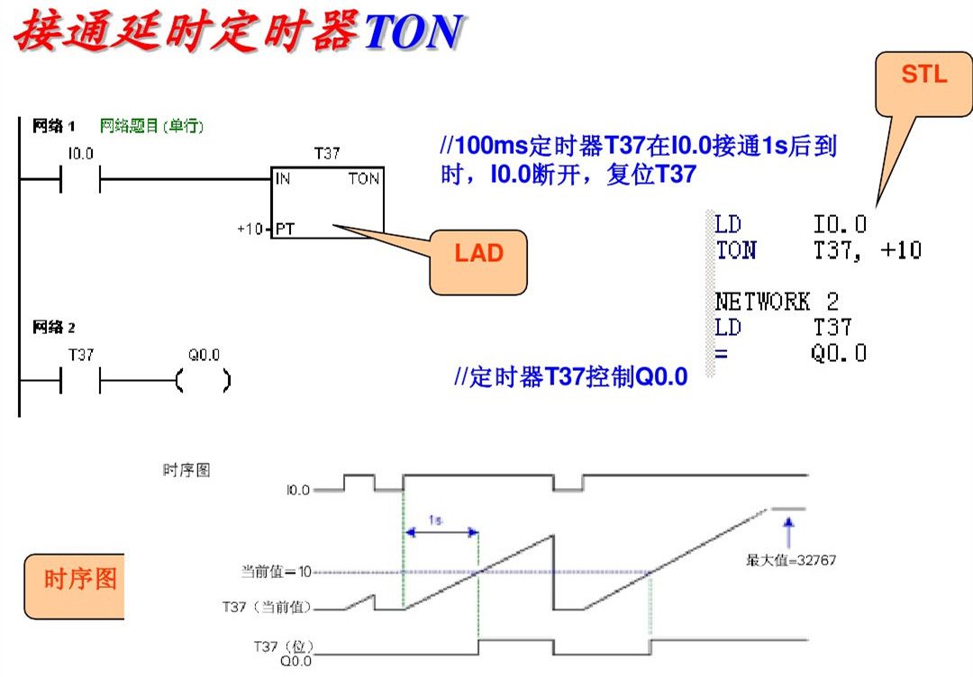
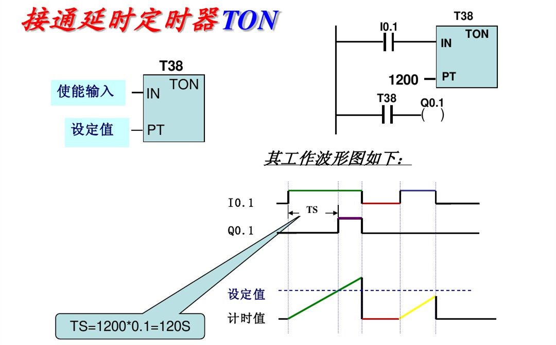
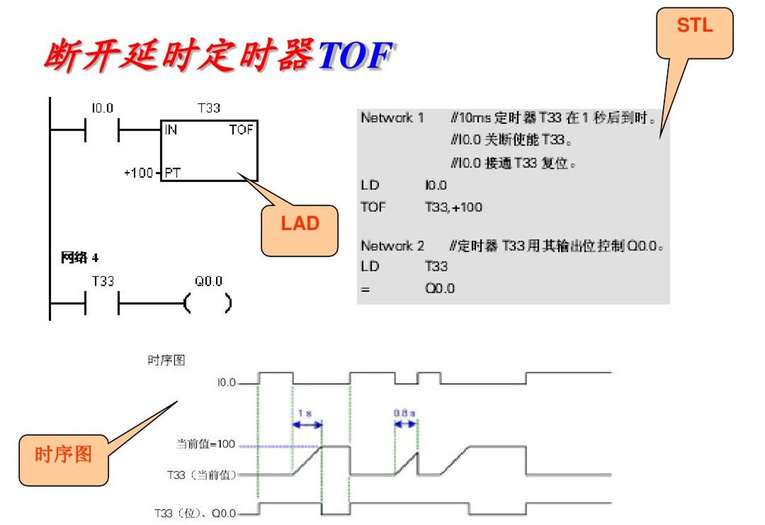
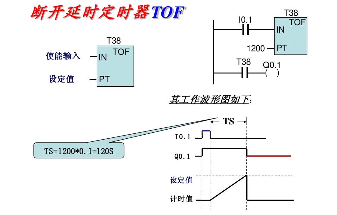
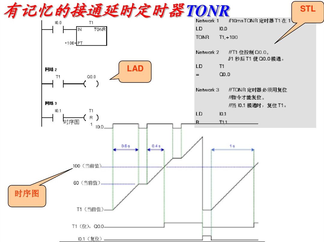
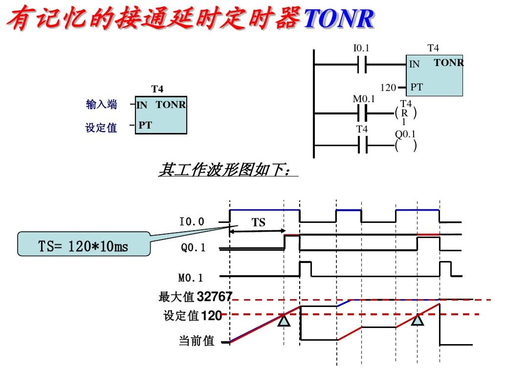
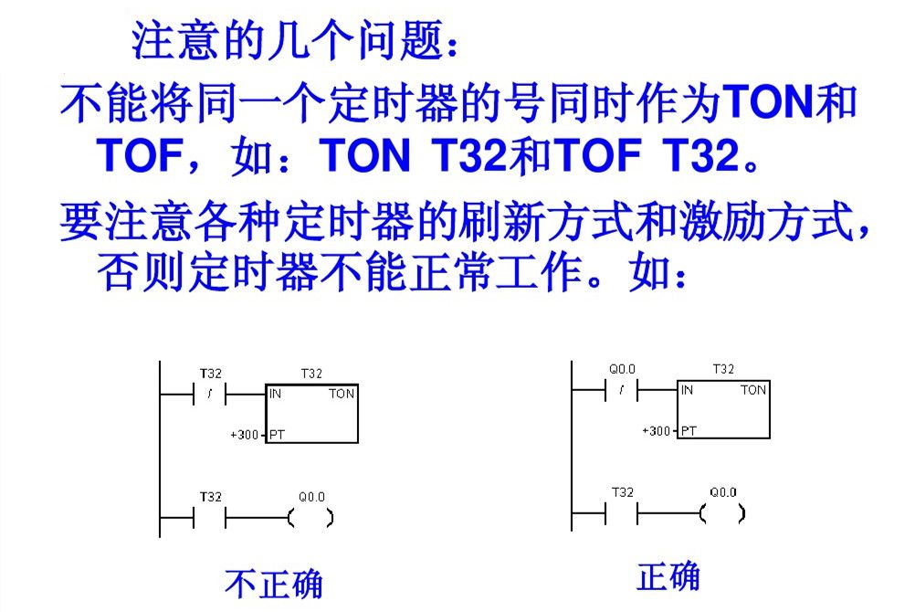
2. Timer Instructions
Includes: On-delay timer (TON), memory on-delay timer (retentive) (TONR), off-delay timer (TOF). The S7-200 has 256 timers (T0~T255).
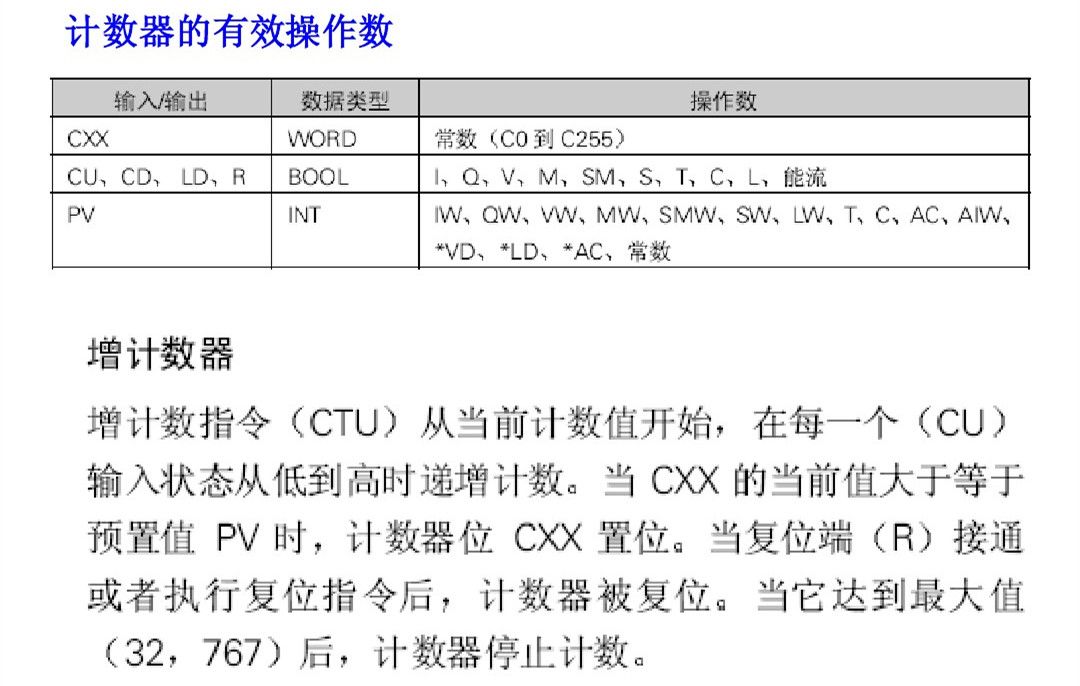
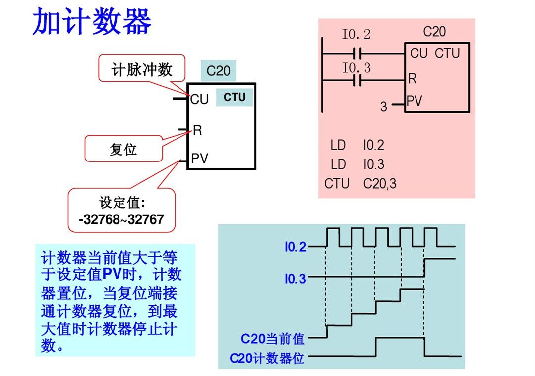
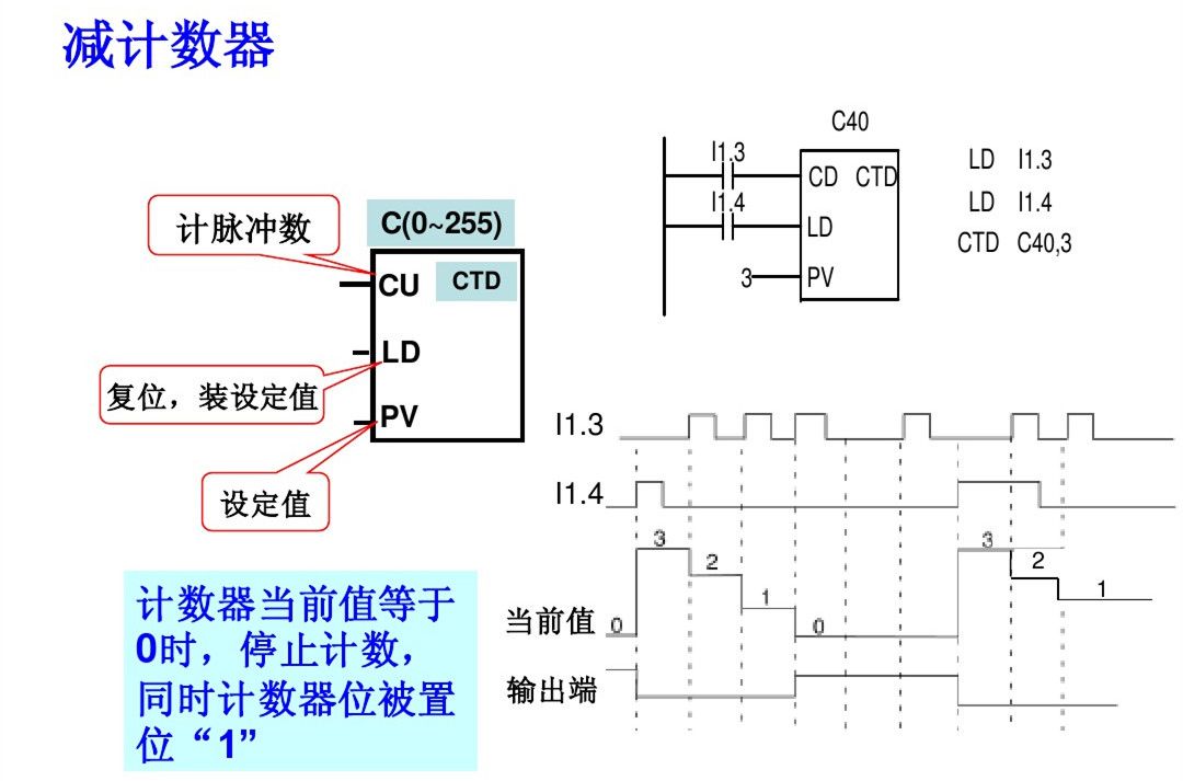
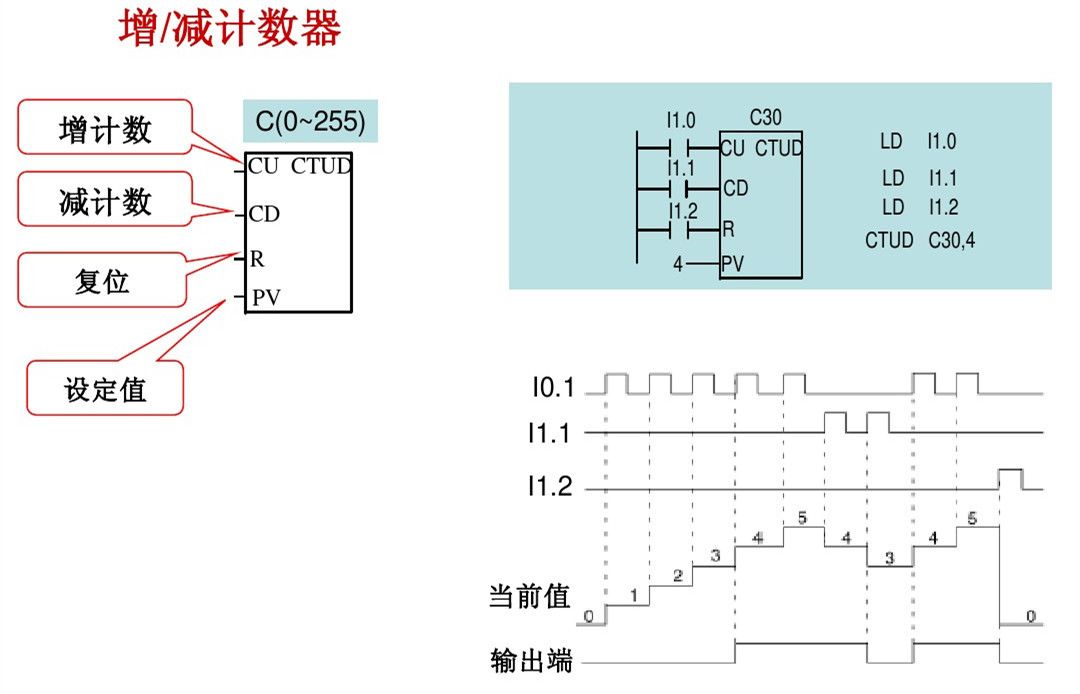
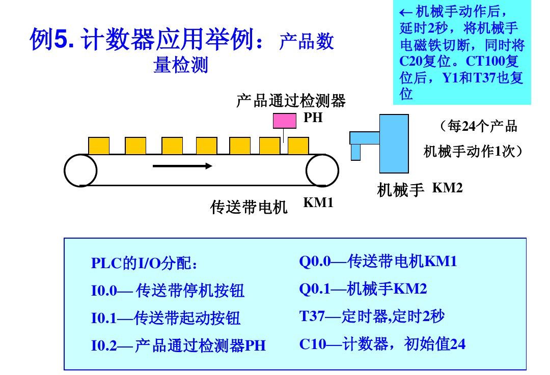
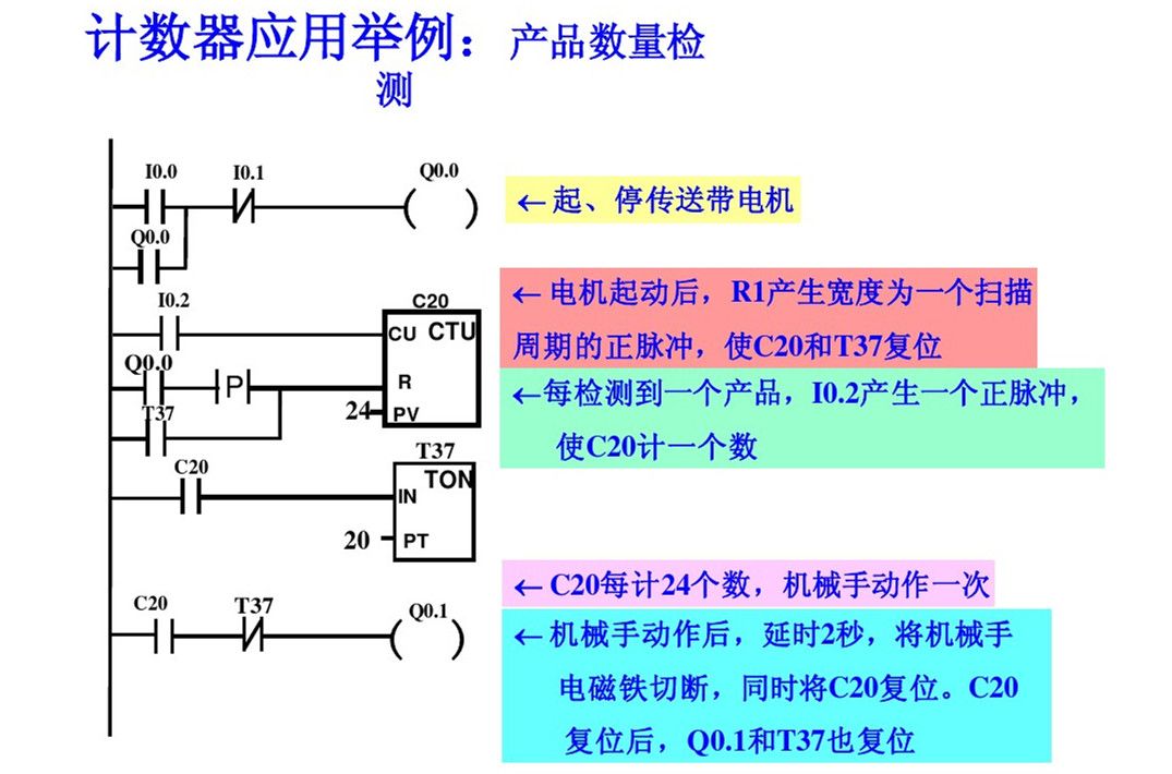
3. Counter Instructions
Includes: Count Up (CTU), Count Down (CTD), and Count Up/Down (CTUD), with a total of 256 (C0~C255). The counter counts the internal clock pulses of the PLC, while the counter counts external or program-generated counting pulses. The current value of the accumulated count (16-bit signed integer) is stored in the counter’s 16-bit current value register.
Each counter has only one 16-bit current value register address. In a program, do not reuse the same counter number, and do not assign it to several different types of counters.

Scan the code to watch PLC video tutorials for free