ver0.2
Introduction
In the previous article, we introduced the basic architecture and routing mechanism of LPI-type interrupts. I believe everyone is now somewhat familiar with LPI-type interrupts, at least understanding the difference between bus-based (Message) and hardwired (Signal) interrupt types. We also discussed the basic architecture and working principles of GIC physical interrupt virtualization. However, is this architecture truly perfect? Are there areas that need optimization? How are LPI-type interrupts virtualized? After optimization, does the GIC virtualization architecture present new issues, and how can these issues be resolved? These topics will be addressed in this article. Before we begin reading this article, I hope everyone will read some preceding articles to get a feel for the content:
(0)[V-00] Introduction to Virtualization – Conceptual Overview
(1)[V-02] Basics of Virtualization – CPU Architecture (Based on AArch64)
(2)[V-05] Basics of Virtualization – Exception Model (AArch64)
(3)[A-25] ARMv8/v9-GIC System Architecture (Hardware Foundations of Interrupts)
(4)[A-26] ARMv8/v9-GIC Interrupt Types
(5)[A-27] ARMv8/v9-GIC Core Components (Basic Components of Interrupt Programming)
(6)[A-28] ARMv8/v9-GIC Interrupt Signal Routing Mechanism and Strategy
(7)[A-29] ARMv8/v9-GIC – Security Architecture Design of the Interrupt Subsystem (Security/FIQ/IRQ)
(8)[A-30] ARMv8/v9-GIC – Interrupt Handling (Interrupt State Machine/Interrupt Lifecycle)
(9)[A-31] ARMv8/v9-GIC – Interrupt Handling (Interrupt Priority/Interrupt Preemption/Interrupt Nesting)
(10)[A-32] ARMv8/v9-GIC – Architecture and Working Mechanism of LPI-type Interrupts
(11)[V-10] ARMv8/v9-CPU Virtualization – Introduction to CPU Virtualization Architecture (vCPU/vPE)
(12)[V-11][A-33] ARMv8/v9-GIC – Interrupt Virtualization Architecture and Working Principles
(13)[A-34] ARMv8/v9-GIC – Routing Mechanism of LPI-type Interrupts (Introduction to PCIE-MSI)
Main Content
1.1 Background
Let us first briefly review the traditional virtualization interrupt system architecture of GIC, as shown in Figure 1-1:
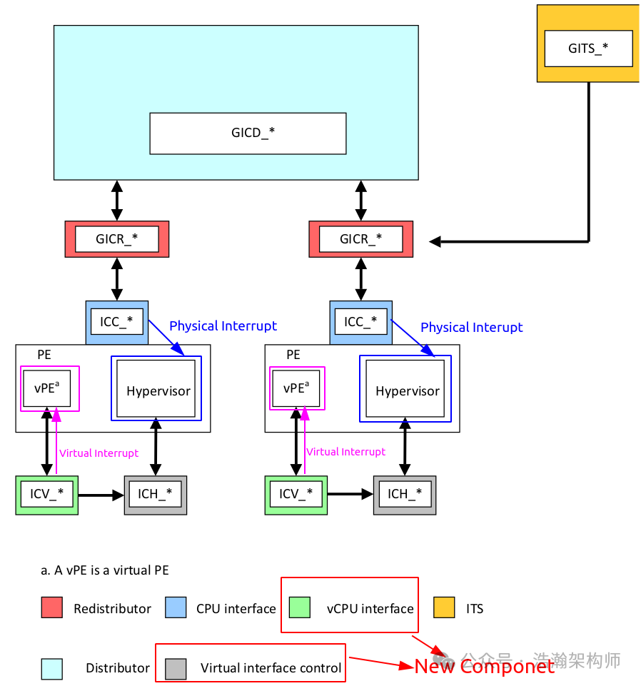
Figure 1-1 GIC Auxiliary Interrupt Virtualization System Architecture
We will not elaborate on the details; you can refer to the preceding articles. By observing the system architecture diagram above, we can identify a key point: under the virtualization software architecture, all physical interrupts (Message & Signal) must first be injected into the Hypervisor, which then re-injects them into the CPU via the GIC’s virtualization auxiliary interface GIC-CPU-Interface (vIRQ & vFIQ). However, at this point, they are no longer the original physical interrupt signals but rather virtual interrupt signals remapped by the Hypervisor. You might think that for the CPU, this is just a momentary event, but the actual situation is not that simple. Let’s shift our perspective back to the ARM Exception model to review the above process (since interrupts themselves belong to a type of exception in the ARM exception model):
When an interrupt occurs, the first issue the system faces under the exception model is which Exception Level (ELx) will handle this exception signal, as shown in Figure 1-2:
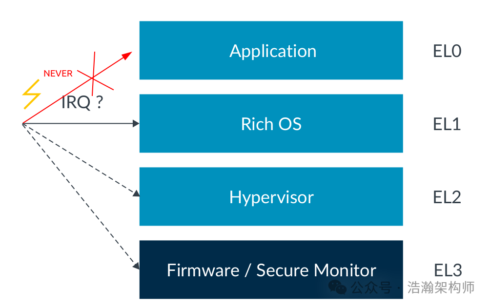
Figure 1-2 GIC Auxiliary Interrupt Virtualization System Architecture
Yes, depending on different configurations (whether virtualization is supported, the current security state of the PE, etc.), IRQ may be responded to by any level except EL0. However, in systems with a virtualization software architecture, it becomes more complicated. According to the previously introduced interrupt virtualization architecture, regardless of the current EL state of the PE (except EL3), all physical interrupt signals are first intercepted and redistributed by the EL2 layer Hypervisor. If the current PE is operating at EL2, that’s fine; if it’s at EL0/1, we need to consider the rules described in the manual:
Each exception type targets an Exception level (EL) to which an exception is taken. Taking an exception therefore enables routing to a different EL. This is particularly important as the only way to gain privilege is by taking an exception. The only way to lose or reduce privilege is by performing an exception return. This means:
• On taking an exception, the EL can stay the same or increase.
• On an exception return, the EL can stay the same or decrease.
As described in the manual, lower versions of the GIC architecture can only have physical interrupt signals processed by the Hypervisor first. If the PE is at EL0/1, this involves switching the Exception Level of the PE, and this switching process is not that simple. Let’s look at the manual’s description:
When an exception occurs, the processor saves the current status of the PE alongside the exception return address, and then enters a specific mode to handle the exception.
A snapshot of the current state is taken from PSTATE, discussed further in the section on Saving the current processor state. This snapshot is written to the Saved Program Status Register (SPSR) and the return address is written to an Exception Link Register (ELR). For synchronous exceptions and SErrors, another register, the Exception Syndrome Register (ESR), is also updated. This records the cause of the exception.
When an exception is taken to an Exception level (ELx) that is using AArch64 state, all of the following occur:
• The contents of PSTATE immediately before the exception was taken is written to SPSR_ELx.
• The preferred exception return address is written to ELR_ELx.
AArch64 has a concept of processor state known as PSTATE; it is this information that is stored in the SPSR. PSTATE contains things like current Exception level and Arithmetical Logical Unit (ALU) flags. In AArch64, this includes:
• Condition flags
• Execution state controls
• Exception mask bits
• Access control bits
• Timing control bits
• Speculation control bits
In summary, when an interrupt arrives, if the PE needs to switch Exception Levels to respond to the IRQ, many tasks must be performed. (Even if responding to an interrupt at the same Exception Level involves related state saving and restoration work.)
So, is this work truly unacceptable for the PE? In most cases, it’s not a big problem; following the architecture in Figure 1-1 is sufficient. However, in certain special scenarios, it may not be so reassuring, such as when a large number of interrupts occur that need to be processed by the VM. At that time, the entire state of the PE is as shown in Figure 1-3.
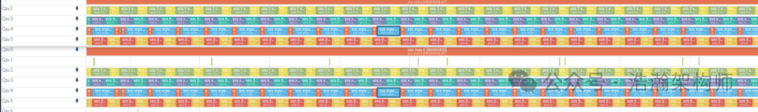
Figure 1-3 PE Working Scenario
The above image has been blurred; please do not focus too much on the details, just listen to me, haha. The reason for the blurring is that this is the daily work of the author, and I do not want you to feel my happiness (especially happy, as I can always restrain myself from smashing my computer). For each PE-Core of the CPU, it must allocate its time slices to various VMs and the Hypervisor. Most of the time and computing power should actually lean towards the VMs because the VMs run business-layer code, which is the software layer closest to the user, such as playback applications or video players. If responding to interrupts frequently forces the PE-Core to perform EL switching, it will lead to the PE constantly saving and restoring contexts, which also consumes system resources. Under normal circumstances, timer interrupts allow the PE-Core to distribute time slices to various system modules at millisecond granularity, such as two VMs’ vCPU threads. However, if physical interrupts surge, the context switching of the PE-Core may be passively reduced, for example, from 10ms to 5ms, or from milliseconds to microsecond-level switching. If it reaches the microsecond level, it is quite burdensome for the system because such conditions amplify many issues (this part requires payment to see, haha). How to understand this? If the switching in Figure 1-3 is at millisecond granularity, it’s manageable; if it’s at microsecond granularity, it becomes problematic and requires optimization. In our traditional virtualization interrupt architecture, each interrupt response requires switching the state of the PE-Core (EL0/1) to EL2. This clearly presents issues in some interrupt-intensive scenarios, leading us to today’s topic: resolving these scenarios by directly injecting virtual interrupts into the VM.
1.2 LPI Interrupt Virtualization Architecture
1.2.1 LPI Interrupt Virtualization System Architecture
In the previous section, we clarified a fact: in some interrupt-intensive scenarios, the traditional virtualization architecture of GIC has room for further optimization. So how can we optimize it? It’s quite simple: let those physical interrupts be injected directly into the VM without going through the Hypervisor, right? Indeed, it’s easy to say, but ARM has helped us with this optimization. In higher versions of GIC (>=4.0), direct injection of interrupt signals into the VM is supported, as shown in Figure 1-4:
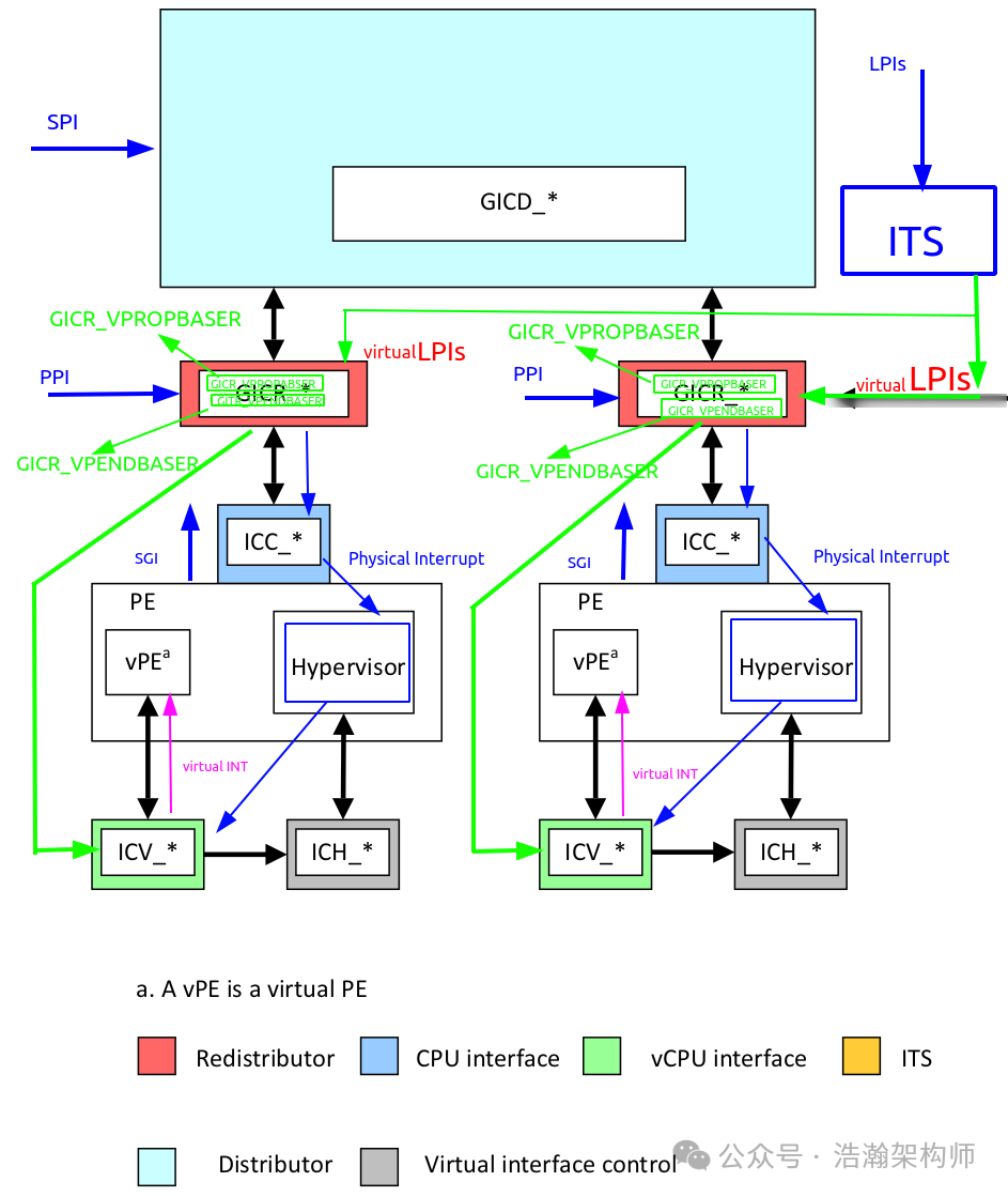
Figure 1-4 GIC Direct Injection of Virtual Interrupts System Architecture
First, it should be noted that interrupts are categorized (SPI/PPI/SGI/LPI). Currently, the GIC architecture only supports LPI and SGI to bypass the Hypervisor and directly inject interrupts into the VM’s vPE. In this article, we will only discuss the LPI-type interrupt virtualization architecture. In this context, let’s look at the system architecture diagram above:
(1) Interrupt types that do not support direct injection still follow the blue path, allowing physical interrupts to sweat it out in the Hypervisor before being re-injected into the vPE through the GIC-VIRT-CPU Interface.
(2) Interrupt types that support direct injection can follow the green path, mapping physical interrupts to virtual interrupts within the ITS, injecting the virtual interrupt and vPEID into the GIC-Redistributor. The GIC-Redistributor performs a state check (virtual interrupt permissions, priority, and vCPU state) before injecting it into the vPE through the GIC-VIRT-CPU Interface.
(3) By comparison, it is evident that the green path incurs significantly less overhead from Exception Level switching than the blue path, thus resolving the performance degradation issue caused by frequent context switching in interrupt-intensive scenarios.
1.2.2 Data Structures
In the previous section, we have roughly understood the framework of direct interrupt injection through the system architecture. In this section, we will enrich some details and discuss the basic principles of how virtual interrupts work, which is essentially the specific method by which GIC implements direct interrupt injection. Unlike traditional interrupts that rely heavily on numerous internal GIC registers, the architecture for implementing direct injection of virtual interrupts introduces some memory-based data structures similar to the ITS’s working method. This section will introduce these data structures. Let’s first look at the manual’s description:
GICv4.1 allows software (Hypervisor) to define a number of virtual PEs (vPE) and map physical interrupts to those vPEs. A vPE is identified by a vPEID (virtual processing element ID). The vPEID is a global identifier, shared by all the Redistributors and ITSs in the system.
The configuration and state of vPEs are stored in memory-based tables, similar to how the configuration and state of physical LPIs are managed. There are three types of memory-based tables used by the Redistributors for managing virtual interrupts:
Virtual LPI Pending Table
There is one Virtual LPI Pending table per vPE. It stores the pending state of virtual interrupts targeting that vPE.
Virtual LPI Configuration Table
The Virtual LPI Configuration Table stores the configuration (enable and priority) of vLPIs. A virtual Configuration table may be shared by multiple vPEs. For example, all the vPEs in one VM might share a Virtual LPI Configuration table.
vPE Configuration Table
The vPE Configuration stores the settings for all vPEs. There is one entry in the table per vPE, storing pointers to that vPE’s virtual Pending and Configuration tables. A vPE Configuration Table entry also stores other information about the vPE, such as how big the vINTID namespace is. A vPE Configuration Table is shared by multiple Redistributors; typically, there is one copy of the table per SoC.
Their logical relationships are shown in Figure 1-5:
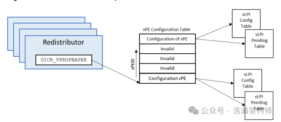
Figure 1-5 Redistributor Memory Structures for vPEs
Next, we will discuss these data structures:
vPE Configuration Table
The number of entries in this table depends on how many vCPU threads the Hypervisor has created for virtual machines and which of those virtual machine threads need to respond to virtual interrupts. A vPE belongs to a VM, and we need a place to record some information about the vPE’s response to virtual interrupts, such as whether there are currently any virtual interrupts on that vPE. This table is completed in the GIC internally through a command from the ITS (note that this command differs between GIC4.0 and GIC4.1):
VMAPP (PEID), (RDADDR), (VPT size), (VPT address), (VCT address),(doorbell)
In this command:
• (vPEID) is the ID of the vPE.
• (RDADDR) is the target Redistributor.
• (VPT address) and (VCT address) are the addresses of the virtual Pending and Configuration.
• (VPT size) specifies the width in bits of the vINTID used for the vPE. From this, the sizes of the Pending and Configuration tables are determined.
• (doorbell) is the physical INTID of the vPE’s Default Doorbell. Specifying 1023 (spurious) means that the vPE has no doorbell interrupt.
Let’s explain the effect of this action, as shown in Figure 1-6:
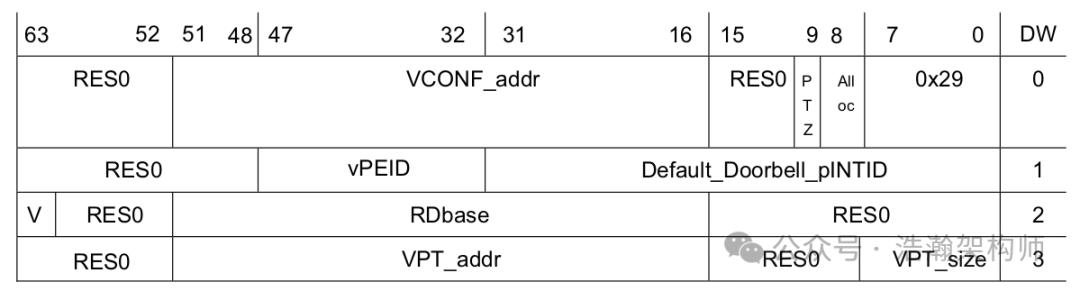
Figure 1-6 VMAPP GICv4.1 Command Encoding
Let’s discuss the core data fields in the VPE configuration table:
(1) vPEID is self-explanatory; it’s the name given to the vCPU. With this ID, the virtual interrupt has a destination.
(2) RDADDR is also easy to understand; no matter how powerful the vCPU is, it must run on a physical CPU, so a fixed position is needed. Since the transmission of interrupts is a hardware behavior within the GIC, the physical CPU location where the vCPU resides must be predetermined. The physical CPU is bound to the GIC-Redistributor, so determining the binding relationship between the GIC-Redistributor and the vCPU also establishes the binding relationship between the vCPU and the physical CPU.
(3) The doorbell will be discussed in a separate article.
Virtual LPI Configuration tables and virtual LPI Pending tables
The formats of the Virtual LPI Configuration tables and virtual LPI Pending tables are consistent with the relevant data formats of physical LPIs. We will not elaborate on this here; you can refer to previous articles or manuals.
GICv4 uses the same concept of memory tables to hold the configuration and pending information for virtual LPIs. The format of these tables is the same as for physical LPIs.
Conclusion
This article focuses on a branch of interrupt virtualization, specifically the topic of direct injection of virtual interrupts. We detailed the defects of the traditional virtualization interrupt architecture under certain conditions and explained the background of the need for direct injection of virtual interrupts. We then introduced the system architecture for direct injection of virtual interrupts into vCPUs and the related core data structures. Due to space limitations, we will separately discuss the software architecture for direct injection of virtual interrupts and the Doorbell mechanism in future articles. Thank you all, and feel free to leave comments, likes, and shares.
Reference
[00] <Armv8-A-virtualization.pdf>
[01] <DEN0024A_v8_architecture_PG.pdf>
[02] <learn_the_architecture_aarch64_exception_model.pdf>
[03] <corelink_gic_720ae_generic_interrupt_controller_trm.pdf>
[04] <arm_generic_interrupt_controller_v3_and_v4_virtualization_guide.pdf>
[05] <learn_the_architecture_generic_interrupt_controller_v3_and_v4_lpis.pdf>
[06] <80-ARM-GIC-wx0005_Arm-gicv3_v4学习这一篇就够了.pdf>
[07] <80-ARM-GIC-wx0003_ARM架构Generic-Interrupt-Controller-GIC之Distributor和CPU-interface.pdf>
[08] <80-ARM-GIC-HK0001-一文搞懂GICv3中断控制器的工作原理.pdf>
[09] <80-ARM-GIC-wx0001_ARM-gicv3_gicv4的总结-基础篇.pdf>
[10] <80-ARM-INT-yk0001_万字长文玩转中断:从硬件看中断之GIC.pdf>
[11] <learn_the_architecture_generic_timer.pdf>
[12] <learn_the_architecture_trustzone_for_aarch64.pdf>
[13] <learn_the_architecture_realm_management_extension.pdf>
[14] <locality-specific_peripheral_interrupts_arm_generic_interrupt_controller.pdf>
[15] <80-HW-PCIE-MSI-cs0001_MSI(Message Signaled Interrupt).pdf>
[16] <80-HW-PCIE-MSI-cs0002_MSI-X详解.pdf>
[17] <NCB-PCI_Express_Base_5.0r1.0.pdf>
[18] <80-HW-PCIE-zh0001_PCIe(1)-PCIe基础概念与设备树.pdf>
[19] <80-HW-PCIE-zh0001_PCIe(2)-配置空间.pdf>
[20] <80-HW-PCIE-cs0001_PCIe中断机制:INTx-MSI与MSI-X的比较与优化.pdf>
[21] <80-Virt-ACRN-INT-I0002_Virtual-Interrupt.pdf>
Glossary
GIC – Generic Interrupt Controller
SCMI – System Control and Management Interface (SCMI)
ACPI – Advanced Configuration and Power Interface (ACPI)
PSCI – Power State Coordination Interface (PSCI)
UEFI – Unified Extensible Firmware Interface (UEFI)
UART – Universal Asynchronous Receiver/Transmitter
SPI – Shared Peripheral Interrupt
PPI – Private Peripheral Interrupt
SGI – Software Generated Interrupts
MPAM – Memory System Resource Partitioning and Monitoring
LPI – Locality-specific Peripheral Interrupt (LPI)
PE – Processing Element
MSI – message-signaled interrupts (MSI)
IAR – Interrupt Acknowledge Registers
EOIR – End of Interrupt Registers
IRM – Interrupt Routing Mode
ITS – Interrupt Translation Service
ITT – Interrupt Translation Tables
vPE – virtual processing element
IPI – inter-processor interrupts
IRI – Interrupt Routing Infrastructure
EOI – End of interrupt
REE – Rich Execution Environment
TEE – Trusted Execution Environment
NMI – Non-Maskable Interrupts
RAZ – Read-As-Zero
WI – Writes Ignored
DTE – Device table entry
ITE – Interrupt translation entry
MSI – Message Signaled Interrupts
PCIe – Peripheral Component Interconnect Express
vPEID – virtual processing element ID