Step control in programming is a very common control method in industrial automation, suitable for sequential execution of process flows. Unlike continuous control, step control allows industrial processes to execute in predetermined steps, ensuring that each process action is completed at the correct time. This article will detail seven practical programming methods for step control, helping you master all techniques from basics to customization.
1. Basic Concepts of Step Control
Step control is essentially a “one step at a time” control method. Imagine you are cooking a dish, where you need to wash the vegetables, chop them, heat the oil in the pan, stir-fry, add seasonings, and finally plate the dish. These actions must be completed in order, cannot occur simultaneously, and cannot be reversed. Many industrial control processes are similar, requiring a series of operations to be executed in a specific sequence.
Core Elements of Step Control:
1. Step Identification: Typically represented by flags (e.g., M0, M1, M2…) or data registers (e.g., D0=1 indicates the first step) to indicate which step is currently being executed.
2. Transition Conditions: Conditions that determine when to transition from the current step to the next step.
3. Step Actions: Specific operations to be executed at each step.
4. Initialization and Reset: Starting and restarting the control process.
2. Traditional Step Control Method – Bit Storage Method
This is the most basic and intuitive step control method, using internal relays (such as Mitsubishi PLC’s M elements, Siemens PLC’s M area) to store the current step.
Working Principle
A series of internal relays (M0, M1, M2…) represent each step, with only one step relay being in the ON state at any time.
Example Ladder Diagram
Practical Application Case
Simple three-step water tank control:
1. First Step (M0): Open the water inlet valve and wait for the water level to reach the mid-level sensor.
2. Second Step (M1): Close the water inlet valve, turn on the heater, and wait for the temperature to reach the set value.
3. Third Step (M2): Maintain the temperature and turn on the stirrer.
Note: When using the bit storage method, ensure that only one step relay is ON at any time; otherwise, it will lead to program confusion. The reset function is particularly important and should be designed with an emergency stop button that resets all step relays.
3. Data Register Method – Step Number Storage Method
Compared to the bit storage method, the data register method is more flexible, especially suitable for control processes with many steps.
Working Principle
A data register (e.g., D0) is used to store the current step number, for example, D0=1 indicates the first step, D0=2 indicates the second step.
Example Ladder Diagram
Practical Application Case
Multi-stage temperature control system:
1. D0=1: Preheating stage, slowly heating to 80℃.
2. D0=2: Constant temperature stage, maintaining 80℃ for 30 minutes.
3. D0=3: Heating stage, quickly heating to 120℃.
4. D0=4: Working stage, maintaining 120℃ for 60 minutes.
5. D0=5: Cooling stage, naturally cooling to below 50℃.
Advantages: Using the data register method allows for easy implementation of complex control logic such as skipping steps and loops, simply by modifying the value of D0. For example, to jump from step 3 to step 5, just execute MOV 5 D0.
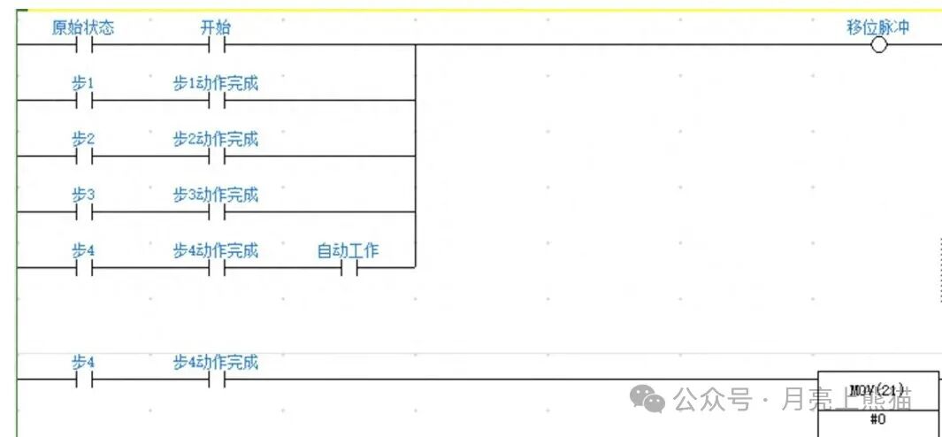
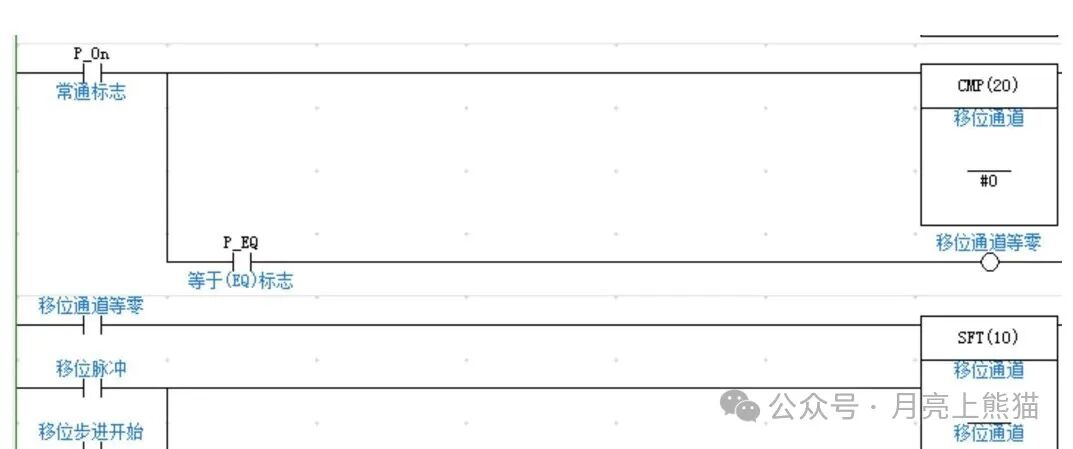
4. State Transition Diagram Method – SFC Programming
The State Transition Diagram (SFC) is one of the five PLC programming languages defined by the IEC 61131-3 standard, specifically designed for step control. Many high-end PLCs directly support SFC programming.
Working Principle
SFC defines steps (Step), transition conditions (Transition), and actions (Action) in a graphical manner.
Graphical Example
Practical Application Case
Packaging assembly line control:
1. INIT: System initialization, device self-check.
2. STEP1: Feeding, waiting for materials to be in place.
3. STEP2: Packaging, waiting for packaging to be completed.
4. STEP3: Sealing, waiting for sealing to be completed.
5. STEP4: Output, waiting for products to be removed.
Note: Although SFC is intuitive, not all PLCs support it. If your PLC does not support SFC, you can simulate the SFC logic using ladder diagrams.
5. Timing Function Instruction Method
Many PLC manufacturers provide dedicated timing function instructions, such as Mitsubishi’s timing function (SFC) instructions and Siemens’ S7-Graph.
Working Principle
Using dedicated instruction blocks to handle step logic simplifies programming.
Code Example (using Mitsubishi FX series as an example)
Where:
– K0: SFC program number
– M100: SFC program start flag
– D0: Step storage area
– D10: Transition condition storage area
– K10: Maximum number of steps
Practical Application Case
Automatic car wash control:
1. Pre-wash spraying.
2. Spraying detergent.
3. Brushing.
4. Rinsing with clean water.
5. Air drying.
Advantages: Using dedicated instructions can significantly reduce the amount of program code and improve the readability and maintainability of the program. However, note that the instructions may differ between different brands of PLCs.
6. Custom Function Block Method
For complex step control requirements, custom function blocks can be created.
Working Principle
Encapsulate the step control logic within a function block, passing control conditions and action outputs through parameters.
Code Example (using Siemens S7-300 as an example)
Practical Application Case
Chemical reaction kettle control:
1. Feeding stage.
2. Heating stage.
3. Reaction stage.
4. Cooling stage.
5. Discharge stage.
Advantages: The function block method allows for modular programming, enabling multiple uses from a single development, greatly improving programming efficiency and program maintainability.
7. State Machine Method – The Most Flexible Custom Step Control Method
A state machine is a theoretical model that is very suitable for implementing complex step control logic.
Working Principle
Abstract the system into a finite number of states, where the system is in only one state at any given time and transitions between different states based on input conditions.
Code Example (using ST language as an example)
Practical Application Case
Injection molding machine control:
1. State 0: Initialization.
2. State 1: Clamping.
3. State 2: Injection.
4. State 3: Holding pressure.
5. State 4: Cooling.
6. State 5: Opening mold.
7. State 6: Ejecting.
8. State 100: Fault handling.
Advantages: The greatest advantage of the state machine method is its flexibility, capable of handling nonlinear control processes, including branches, loops, and exception handling. Moreover, separating states from actions makes the program structure clearer.
Common Problems and Solutions
1. Steps Stuck and Not Advancing
Cause: Usually due to unmet transition conditions or condition signals being too short.
Solution: Check if the sensors for the transition conditions are functioning properly; consider using edge detection instead of level detection; add a condition self-locking circuit to extend the signal.
2. Multiple Steps Activated Simultaneously
Cause: Issues with reset logic or competition conditions in the program.
Solution: Ensure that each step is correctly reset when transitioning; for the bit storage method, consider placing all step bits in one network to ensure mutual exclusivity.
3. Unable to Recover Correctly After Emergency Stop
Cause: Incomplete design of emergency stop logic.
Solution: Design a complete emergency stop and recovery process, including step reset, confirmation of equipment safety position, and a gradual recovery process.
4. Program Difficult to Expand and Modify
Cause: Unreasonable structure and high coupling between steps.
Solution: Adopt a modular design, consider using function blocks or state machine methods; clearly document the functions and conditions of each step.
Practical Exercise Suggestions
1. Start Simple: First, implement a simple control of 3-5 steps using the bit storage method, such as a three-color lamp cycling control.
2. Simulate Real Scenarios: Use buttons and indicator lights to simulate sensors and actuators, constructing scenarios like filling lines or elevator control.
3. Record and Analyze: Use the PLC’s online monitoring function to observe the step transition process, record the program’s running trajectory, and analyze whether it meets expectations.
4. Gradually Increase Difficulty: After mastering the basic methods, try to implement complex control logic such as skipping steps and branching.
5. Mix Multiple Methods: In a more complex project, try combining different step control methods to experience their respective advantages and disadvantages.
6. Challenge Exception Handling: Intentionally create abnormal situations (such as sensor failure) to test the robustness of the program.
7. Refer to Industrial Standards: Understand the ISA-88 batch control standard and benchmark step control programs against industry practices.
Start Simple: First, implement a simple control of 3-5 steps using the bit storage method, such as a three-color lamp cycling control.
Simulate Real Scenarios: Use buttons and indicator lights to simulate sensors and actuators, constructing scenarios like filling lines or elevator control.
Record and Analyze: Use the PLC’s online monitoring function to observe the step transition process, record the program’s running trajectory, and analyze whether it meets expectations.
Gradually Increase Difficulty: After mastering the basic methods, try to implement complex control logic such as skipping steps and branching.
Mix Multiple Methods: In a more complex project, try combining different step control methods to experience their respective advantages and disadvantages.
Challenge Exception Handling: Intentionally create abnormal situations (such as sensor failure) to test the robustness of the program.
Refer to Industrial Standards: Understand the ISA-88 batch control standard and benchmark step control programs against industry practices.
Finally, remember this saying from experienced engineers: A good step control program should be as clear as telling a story, so that any maintenance personnel can understand at a glance what the program is doing.
Whether you are a beginner or an experienced engineer, mastering these seven step control methods can greatly enhance your PLC programming skills and engineering implementation efficiency. Choose the most suitable method based on project requirements and personal habits, or even create your own step control method!