【Action Description】
As shown in Figure 2-5-1, a sewage tank is equipped with two sewage pumps for the discharge treatment of sewage, with the following specific control requirements:
1) Long press the start button for 3 seconds to start the device, the running indicator light Y1 (green light) will light up. Press the button a second time to stop the device, and the running indicator will turn off.
2) The two sewage pumps will work in a timed cycle, switching pumps every 5 minutes.
3) When the sewage level is high, the sewage pump will automatically turn on; when the sewage level is low, the sewage pump will automatically turn off; when the sewage level reaches an ultra-high level, both pumps will start running simultaneously.
4) Alarm output: when the level is at the ultra-high level, the level alarm light (yellow light) Y0 will flash at intervals of 0.5 seconds; when the level is at the ultra-low level, the level alarm light (yellow light) will stay on.
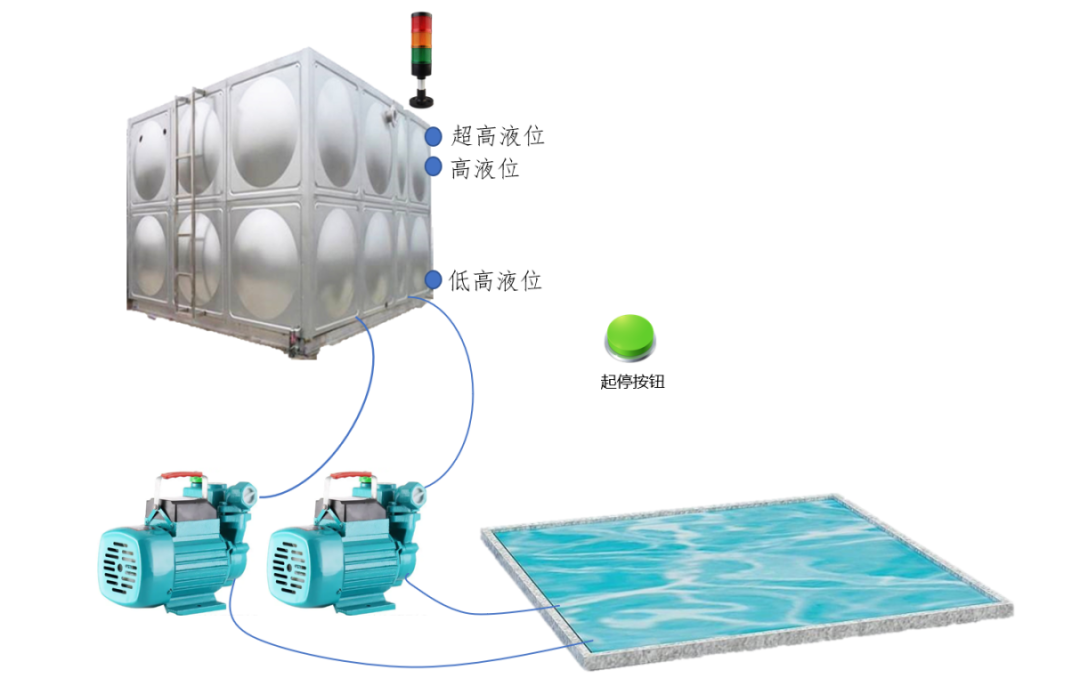
Figure 2-5-1 Device Schematic
【I/O Allocation】
The I/O allocation is shown in Table 2-5-1, with 4 input points and 4 output points.
Table 2-5-1 I/O Allocation
|
Input Point |
Comment |
Output Point |
Comment |
|
X0 |
Start |
Y0 |
Alarm |
|
X1 |
High Level |
Y1 |
Running Indicator |
|
X2 |
Low Level |
Y2 |
Pump 1 |
|
X3 |
Ultra-High Level |
Y3 |
Pump 2 |
【Program Development and Ideas】
1. Start/Stop Control
The start and stop program is shown in Figure 2-5-2, using timer T0 to time the start button. When the time is up, it sets the running indicator light Y1. Under the condition that the running indicator light is on, pressing the start button again will trigger the reset instruction to reset Y1.
When the liquid level is at the specified level, Y1 will be automatically set to control the start of operation;
When the operation just starts, Y2 will be set to start Pump 1, serving Y3 for Pump 2.
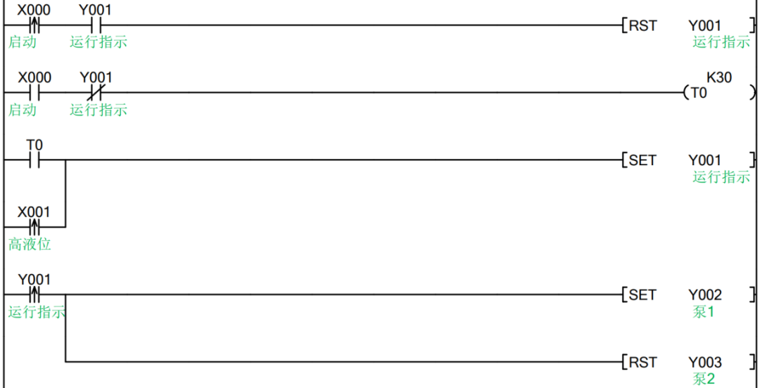
Figure 2-5-2 Start/Stop Control
2. Pump Cycle Control
The pump cycle control is shown in Figure 2-5-3, when encountering high level X1, the rising edge of X1 will turn on once, using the set instruction to start Pump 1 (Y2), while using the reset instruction to reset Pump 2 (Y3);
When Pump 1 starts, the corresponding Y2 normally open contact will be turned on, using T1 to time it for 5 minutes (K3000). When the time is up, the normally open contact of T1 will be turned on, resetting Y2 (stopping Pump 1) while setting Y3 (starting Pump 2);
When Pump 2 starts, the corresponding Y3 normally open contact will be turned on, using T2 to time it for 5 minutes (K3000). When the time is up, the normally open contact of T2 will be turned on, resetting Y3 (stopping Pump 2) while setting Y2 (starting Pump 1).
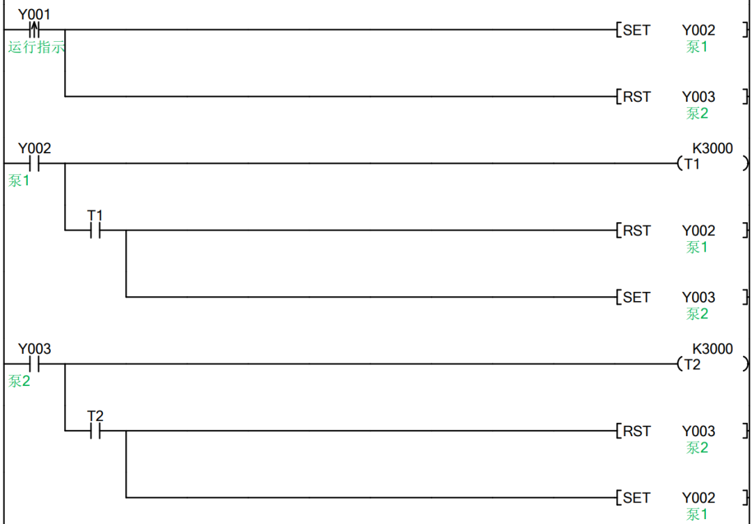
Figure 2-5-3 Pump Cycle Control
3. Ultra-High Level Control
The control for ultra-high level is shown in Figure 2-5-4, when the ultra-high level signal is on, using the set instruction to set both Y2 and Y3, both pumps can start simultaneously. It is important to note that this segment of the program should be placed after the previous segment controlling the pump cycle, as the program scans from top to bottom, with the last line being the standard.
Then, when the water level is below the ultra-high level, the falling edge of the ultra-high level will have a signal, which we use to reset Pump 2 (Y3). Note that the following two lines of code also cannot be reversed.
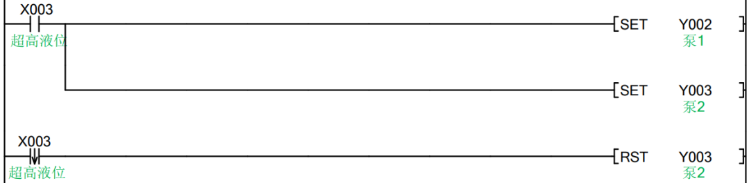
Figure 2-5-4 Ultra-High Level Control
4. Stop Control
The stop control program is shown in Figure 2-5-5, when the running signal is disconnected, the normally closed contact of Y1 will turn on, or when the liquid level is below the lower level, the normally closed contact of X2 will also turn on. In this case, all motors need to be stopped, using the batch reset instruction ZRST to reset Y2 and Y3 together, achieving the stop effect. Similarly, due to the scanning cycle, the program execution is based on the last line, so this segment of the program should be written after the previous segment; otherwise, when the liquid level is ultra-high, regardless of whether it is stopped, both motors will automatically start.
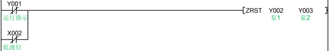
Figure 2-5-5 Pump Cycle Control
5. Alarm Control
The alarm control program is shown in Figure 2-5-6, when the liquid level is at the ultra-high level (X3 is on), in series with M8013 normally open contact (M8013 has a cycle of 1 second pulse signal, which will be on for 0.5s and off for 0.5s), thus achieving the 0.5s interval flashing effect; when the liquid level is below the ultra-low level, the sensor of X2 will not sense the liquid, so the normally closed contact of X2 will close, and we will parallel this signal to control the level alarm light Y0.
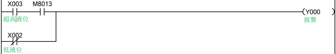
Figure 2-5-6 Alarm Control
For the source program, you can scan the QR code to obtain it for free, the 6th file in the QR code.