Follow+Star Public Account Number, don’t miss out on exciting content
Source | Renesas Embedded Encyclopedia
To enhance the security of MCU projects, it is crucial to set safety boundaries. This article discusses the method of setting IDAU safety boundaries using the Renesas RA6M5 (Qiming 6M5 Development Board) and Renesas Flash Programmer programming tool as examples.
When the MCU chip is shipped, its DLM state is set to “CM” by default, and the IDAU safety boundary is not configured. In this state, users can normally use most peripherals of the chip, except for a few peripherals, such as Ethernet (ETHERC and EDMAC). Therefore, it is necessary to change the chip’s DLM state to “SSD”.
The specific steps for dividing IDAU boundaries related to the Trustzone security feature are as follows:

Step 1: First, compile the project
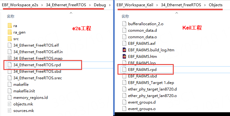
First, compile the project. After a successful compilation, a file with the .rpd extension will be generated in the compilation output folder. This file is actually the Renesas Partition Data File. As shown in the figure below.
Step 2: Switch the chip’s DLM state
According to the content of section 3.5 above, use the Renesas Flash Programmer software to change the chip’s DLM state.
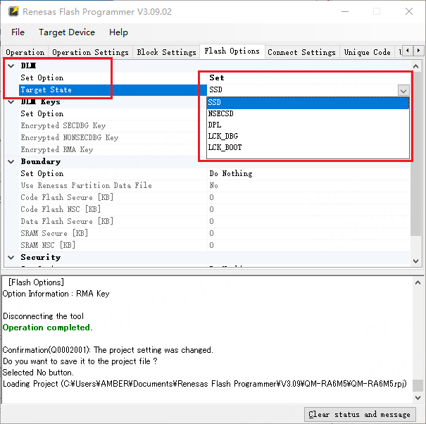
Alternatively, you can also set the DLM state to “SSD” in the Flash Options tab as shown in the figure below:
Step 3: Select the project .rpd file and set the boundary
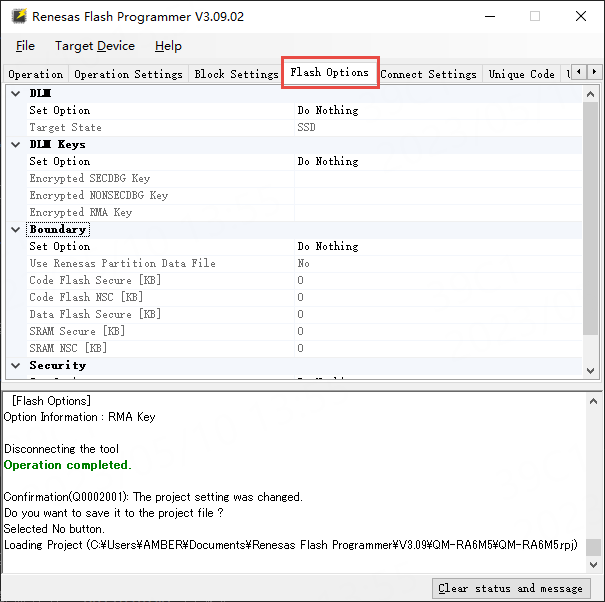
Switch to the Flash Options tab as shown in the figure below:
Set the boundary (Boundary) as shown in the figure below:
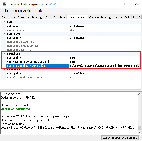
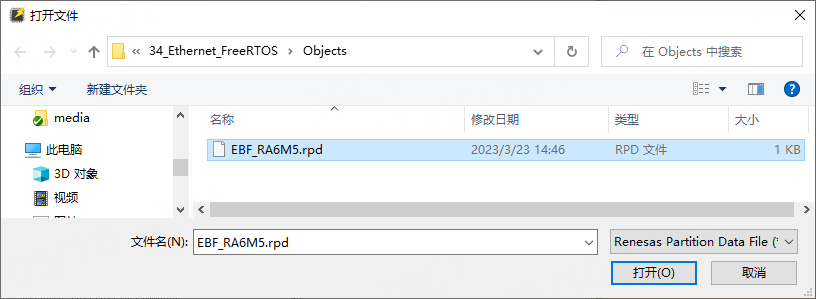
In the above figure, you need to select the .rpd file generated after compiling the project in the “Renesas Partition Data File” box. As shown in the figure below.
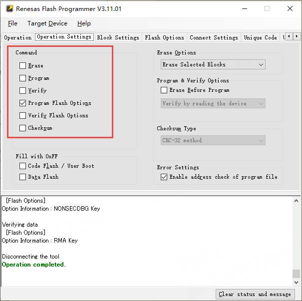
Then, as shown in the figure below, uncheck “Erase”, “Program”, and “Verify” under the Operation Settings tab, and check “Program Flash Options”.
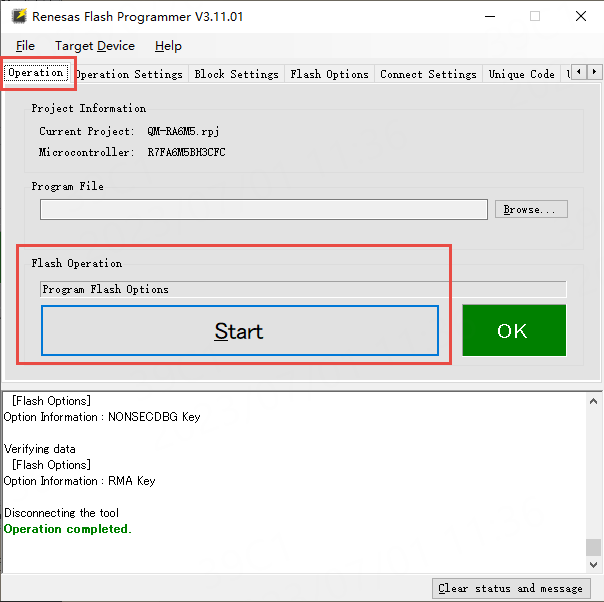
Switch back to the Operation tab and click the large Start button to execute the selected operations:
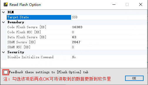
Next, you can use “Read Flash Options” to read the chip’s Flash Options. Follow the operation shown in the figure below.
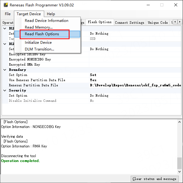
The result of the “Read Flash Options” operation will pop up a window. This window displays the current DLM state of the chip, as well as the security/non-security boundary division of Code/DataFlash and SRAM. As shown in the figure below.
Finally, you can download the program of the Ethernet example to the development board and use the Ethernet function normally.
What is the meaning and function of TrustZone in the Cortex-M85 (RA8) microcontroller?
Renesas Electronics launches automotive MCU with integrated low-power Bluetooth
Lightweight open-source face recognition algorithm based on MPU