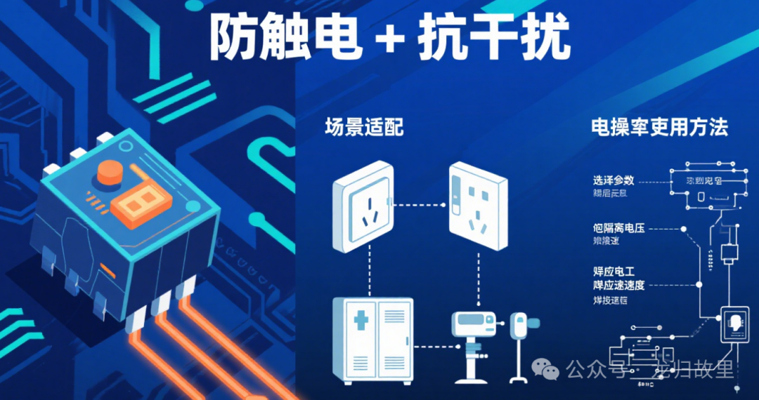
1. Function Definition
An optocoupler (光电耦合器, Optocoupler) is a semiconductor device that achieves electrical signal isolation and transmission through optical signals. Its core functions are electrical isolation and signal transmission.
It consists of two parts:
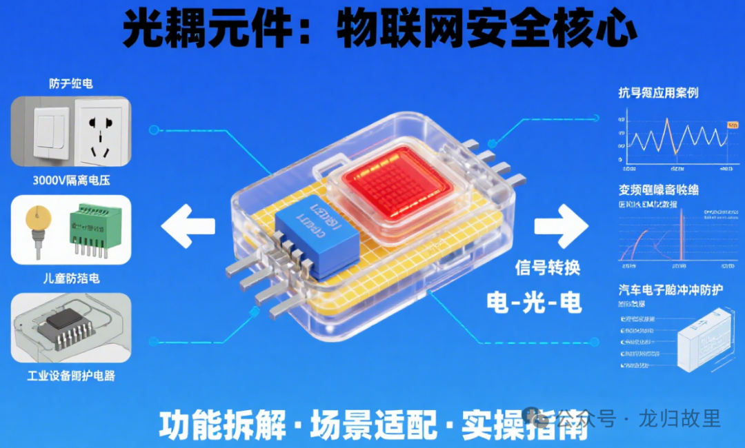
•Input side (light-emitting side): Typically a light-emitting diode (LED), which converts electrical signals into optical signals;
•Output side (light-receiving side): Typically a phototransistor, photodiode, or thyristor, which converts optical signals back into electrical signals.
Through the conversion of “electric – light – electric” signals, the optocoupler can achieve electrical isolation (no direct electrical connection) between the input and output circuits, thereby blocking common-mode interference, suppressing noise, and isolating high and low voltage domains, protecting sensitive circuits (such as microcontrollers in IoT devices).
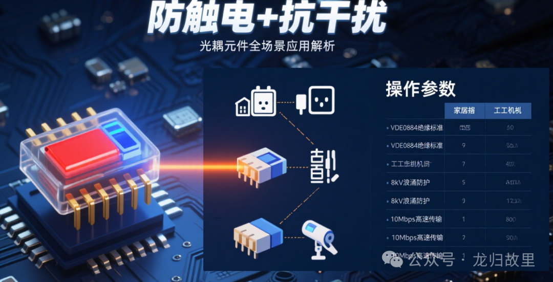
2. Typical Use Cases in IoT Scenarios
In Internet of Things (IoT) systems, devices often need to connect to modules with different voltage levels (such as sensors, actuators, and power supplies) and may be in environments with strong electromagnetic interference (EMI, such as industrial sites or smart home high-voltage scenarios). The isolation characteristics of optocouplers make them key components, with typical scenarios including:
1.Isolation between sensors and controllers
In IoT devices, some sensors (such as industrial pressure sensors and current sensors) may operate in high voltage or strong interference environments. Optocouplers can isolate interference signals on the sensor side, ensuring clean signal transmission to low-voltage MCU (such as ESP32, STM32), avoiding data misjudgment caused by interference.
2.Control of high-power actuators
In smart homes (such as smart switches and curtain motors) or industrial IoT (such as relay and solenoid control), actuators are often directly connected to 220V AC power, while controllers (MCU) operate at 3.3V/5V low voltage. Optocouplers can isolate the high-power circuit from the low-voltage control circuit, preventing high voltage from damaging the MCU, while also avoiding strong electrical noise interference with control signals.
3.Isolation of power modules
In IoT gateways or multi-node devices, if there are multiple independent power domains (such as 12V sensor power and 3.3V MCU power), optocouplers can be used in conjunction with isolated power supplies to achieve signal transmission between domains, avoiding power noise coupling.
4.Isolation of communication interfaces
In IoT devices, bus communications such as RS485 and CAN are susceptible to ground potential differences or electromagnetic interference over long distances. Optocouplers can isolate the bus side from the device side circuit, reducing communication error rates and protecting device interfaces.
3. Component Usage (Selection and Circuit Design)
1. Selection Key Points
IoT devices are usually sensitive to size, power consumption, and cost, so selection should focus on the following parameters:
•Isolation Voltage: Choose based on scene requirements (e.g., home scenarios ≥2.5kV, industrial scenarios ≥5kV);
•Transmission Rate: Low-speed signals (such as sensor data) can use standard optocouplers ( ≤100kHz), while high-speed communication (such as buses) requires high-speed optocouplers ( ≥1MHz);
•Current Transfer Ratio (CTR): The ratio of output current to input current, which needs to match the input driving capability (e.g., MCU ‘s GPIO output current is typically 10-20mA);
•Package: Prefer small packages (such as SOP-4, DIP-4), suitable for the compact design of IoT devices.
2. Typical Circuit Design
Taking “MCU controlling a relay” as an example (the most common scenario in IoT), the circuit design is as follows:
•Input Side: The GPIO of the MCU connects to the input terminal of the optocoupler (LED), in series with a current-limiting resistor R1 (calculation: R1=(Vcc – Vf)/If, where Vcc is the GPIO voltage, Vf is the forward voltage drop of the LED ≈1.2V, and If is the operating current of the LED ≈10mA);
•Output Side: The output terminal of the optocoupler (phototransistor) connects to the relay coil, requiring a flyback diode D1 (to protect the transistor from damage due to back EMF from the coil), and powered by Vdd (such as 12V).
Notes:
•The input side and output side must use independent power supplies (e.g., 3.3V MCU power for input and 12V relay power for output), otherwise true isolation cannot be achieved;
•During PCB layout, the input circuit and output circuit must be physically separated (to avoid crossing), reducing electromagnetic coupling;
•If driving high current loads (such as motors), a power transistor (such as a bipolar transistor or MOSFET) should be added on the output side of the optocoupler to increase current.
Conclusion
Optocouplers play the role of a “safety guard” and “anti-interference barrier” in IoT devices through their electrical isolation characteristics, especially suitable for scenarios with mixed high and low voltages and strong interference. When selecting components, it is essential to match the isolation level with transmission requirements, and in circuit design, attention must be paid to power isolation and layout specifications to ensure the stability and safety of IoT systems.
IGBT (Insulated Gate Bipolar Transistor) Function Usage and Application Scenarios ExplainedIoT Component Rectifier Bridge: From Basic Functions to Smart Scene Energy HubsFunction, Usage, and Application Scenarios of IoT Component TransformersIoT Power Conversion DevicesCore IoT Component MOS Devices: Analyzing Their Full-Scene Applications from Smart Sockets to Medical DevicesBuzzer: The Guardian of Safety in the IoT EraIntroduction to IoT Component Connectors and Their Functional Usage ScenariosCore IoT Components: How Transistors Empower Smart Devices“Electronic Valves” in the IoT Era: How Diodes Reshape the Smart World?Fuse Components in IoT: Concepts, Uses, and Application ScenariosBasic IoT Components – Resistor Function and Usage Introduction, the “Cornerstone” Component in CircuitsApplication of Breadboards in IoTUsage and Application Scenarios of IoT Inductor Components Explained in DetailDupont Wires: Essential Tools for Electronic ConnectionsIoT: The Core Driving Force Behind Building a Smart World