Most designers in the robotics industry have encountered URDF files, and exporting URDF files is an essential skill for mechanical structure engineers in the robotics field. This article is divided into three parts to explain my method of exporting URDF files.First, there are various software plugins for automatic export. Currently, most robotic engineers use SolidWorks for modeling, which has a mature export plugin called SW2URDF. The operation process will not be described here; please refer to the following article: Detailed Tutorial on URDF for Robot Dogs V1.0.For other software’s automatic export plugins, you can refer to the following download link: [ROS2] Intermediate: URDF – Generating URDF Files. The software used by the author is CREO, and the following text mainly explains the manual export method for CREO. Once mastered, you can design your own plugin for automatic export in CREO.Now, let’s formally introduce:1. Understanding URDFExplanation of URDF files: a Unified Robot Description Format. The simplest explanation for CAD engineers is that URDF ≈ STEP. It is an XML format language that describes the information of your designed drawings using programming language.For example: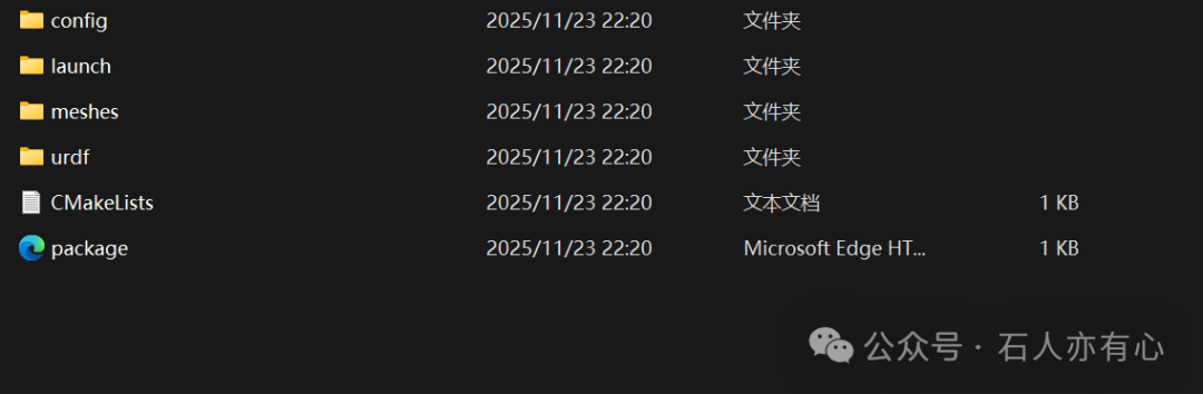 This is the URDF file exported from SolidWorks that I downloaded from GitHub. This is the target that the mechanical structure engineer needs to deliver to the algorithm. It can be seen that it contains four folders, each corresponding to different information: the config folder which CREO users are familiar with, serves the same purpose, storingjoint control parameters, sensor calibration data, algorithm configuration files, etc. An example here is a YAML file.
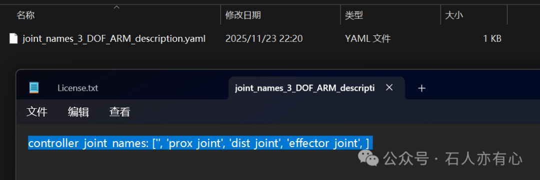 When opened with Notepad, it shows only one line of description, defining the joint names. Of course, the order matters, which can be understood as the model tree in CREO.The launch folder contains the launch files, which arethe visualization and state publishing launch files and the simulation launch files.
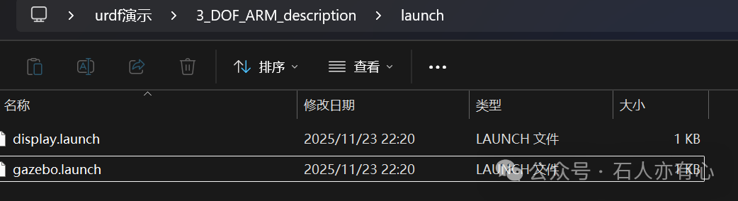 Here we can ignore it; the algorithm will handle it. If there are issues during testing, check the language of the specified file location.
 The meshes folder contains STL files, mainly used for rendering. The graphical display relies on this part of the files, which CAD engineers are likely familiar with.The urdf folder contains the URDF files and a table, which is the core that CAD engineers need to handle.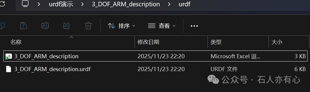
 The above shows the content in the table, which exports the parameters of the joint links, including center of mass coordinates, origin coordinates, mass parameters, inertia matrix, angle limits, etc. These can be set by yourself, just for convenience in viewing the data.The URDF file below will not be elaborated on for now.
<span><span>CMakeLists file</span></span>is the configuration file for the CMake build system, which can be ignored.<span><span>package</span></span> file is the description file for the ROS package, which can also be ignored.2. Validating URDFHaving introduced our target, what does this file look like when opened, and how can we validate whether our URDF is correct? The fastest way is to directly search for a URDF viewer online and drag and drop to check. For example, http://urdf.robotsfan.com/ to view example files. You can observe that our model is generated on the webpage, and dragging the joints is also correct, which initially indicates that the exported URDF file format is correct.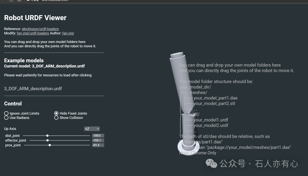 Of course, if you have installed a Linux system, you can directly use RViz on ROS to validate, or you can also use Gazebo and Mujoco for validation, but remember to turn off gravity during validation. Since my new computer has nothing installed except CREO, I will not demonstrate it for now.Through the above introduction, I believe that you, as a master craftsman, already have a preliminary understanding of the target to be delivered. The next article will demonstrate how to manually modify URDF in CREO, and there will be another article on URDF output from other tools, allowing those who are not SW users to easily export URDF files.