Fill in the DTS based on the schematic
The schematic describes the hardware from the perspective of IO signals, which are strongly correlated with the PHY’s index. As mentioned earlier, the controller and PHY index of the RK3588 may not be consistent, so special attention is needed when reviewing the schematic. Here are some suggestions for filling in the DTS, along with examples of how to map the PHY and controller from the schematic to the DTS nodes.
Recommended steps for filling in the DTS based on the hardware schematic:
1. Confirm with the hardware engineer how many PCIe devices are used and how the multiple PCIe interfaces of the chip are allocated;
2. In the schematic, find out which PHY output corresponds to the PCIe data lines used by a specific device;
3. Determine which controller and PHY are used by the current device and enable them in the DTS;
4. Ensure that the “phy” property and mode of the controller used by the current PCIe interface are correctly selected, for example, the pcie2x1ln controller needs to select comboPHY and specify it as PHY_TYPE_PCIE;
5. Confirm whether the current PHY has multiple operating modes and whether the configuration is correct, such as the different split combinations of pcie30phy needing to be correctly configured for the corresponding mode;
6. Determine which GPIO is used for the “PERSTn” signal of the current PCIe interface and correctly configure it to the controller DTS node;
7. Identify which GPIO controls the “PWREN” signal of the current PCIe interface and correctly configure it to the controller DTS node (this configuration can also be placed in the DTS of the onboard peripherals);
8. Configure the hardware required for the operation of other peripherals;
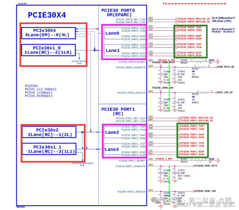
The following diagram shows the RK3588 pcie30phy and its possible controllers, with the red box indicating the controller, the pink box indicating the PHY signals, and the green box indicating the peripheral signals. The actual controller used can be confirmed through the peripheral signal connections or verified with the hardware engineer for correctness. The diagram is from the RK3588 evb1, where the device is connected to a PCIe 3.0 x4 slot, so the controller used is PCIe30X4 (named pcie3x4 in DTS), and the other controllers are not used in conjunction with this PHY.
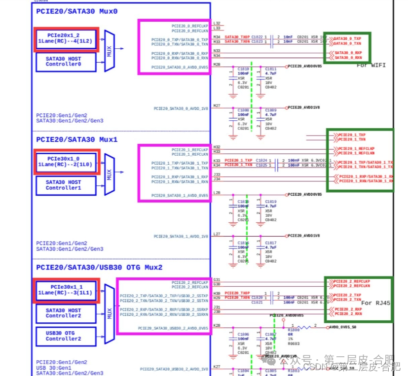
The following diagram shows the RK3588 comboPHY and its possible controllers, with the red box indicating the controller, the pink box indicating the PHY signals, and the green box indicating the peripheral signals. The actual controller used can be confirmed through the peripheral signal connections or verified with the hardware engineer for correctness. In this diagram, the PHY of Mux0 (combphy0_ps) operates in SATA mode and does not operate in PCIe; the PHY of Mux1 (combphy1_ps) may operate in PCIe mode with PCIe30x1_0 (named pcie2x1l0 in DTS), which needs to be determined by the actual device connected; the PHY of Mux2 (combphy2_psu) works in PCIe mode with PCIe30x1_1 (named pcie2x1l1 in DTS) to connect to a PCIe network card.