Virtualization is a broad term that generally refers to the operation of computing components on a virtual rather than a physical basis. It is a solution aimed at simplifying management and optimizing resources. Server virtualization is a technology used to integrate x86-based servers to improve resource utilization and performance.
This article focuses on analyzing the characteristics of virtual network cards, SR-IOV, NUMA, and virtual disk formats under the x86 architecture from the perspective of enterprise business systems and management. It explores resource allocation and performance optimization solutions in different application scenarios, hoping to enhance the performance and resource utilization efficiency of x86 servers through practical applications and optimal configurations across multiple systems.
1
Two Common Architectures of x86 Virtualization
There are two common architectures for x86 virtualization: hosted architecture and bare-metal architecture. The hosted architecture runs the virtualization layer on top of the operating system as an application, providing broad support for hardware. In contrast, the bare-metal architecture runs the virtualization layer directly on the x86 hardware system, allowing direct access to hardware resources without needing to go through the operating system, thus achieving higher efficiency.Vmware Workstation and VMware Server are both implemented based on hosted architecture, while VMware ESX Server is the industry’s first bare-metal virtualization product, now in its fifth generation. ESX Server must run on VMware-certified hardware platforms and can provide outstanding performance, fully meeting the performance requirements of large data centers. This article primarily discusses resource allocation and performance optimization issues based on the x86 bare-metal architecture.
2
Three Levels of Resource Allocation in x86 Virtualization
Simply put, resource allocation for servers includes three levels: network, computing, and storage.Each virtual machine (VM) operates within its connected network, undertaking certain computing tasks and storing the processed data for business use.
Network Level
From the network perspective, the x86 physical machine uses physical network cards connected to physical switches. When an x86 machine is divided into multiple VMs, virtual network cards and virtual switches are created. This generates traffic transmission and interaction between the virtual and physical networks, as shown in Figure 1.
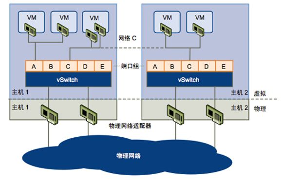
Figure 1 Virtual Network and Physical Network
The VMs divided on the same physical machine can be categorized into the same subnet and different subnets. Depending on whether the network traffic between VMs passes through the physical network card, there are four different scenarios:
In the first scenario, for example, if the VMs of a business system are on the same host and subnet, then the network traffic between the VMs does not pass through the host’s physical network card, with a maximum network traffic of 7.6GB. (Testing method: Enable jperf server on testvm1 as the network data receiver, enable jperf client on testvm2 to connect to jperf server to send network packets while applying pressure on the network traffic. The x86 host has dual 10G network cards.)
In the second scenario, for instance, if the VMs of a business system are on the same host but in different subnets, then the network traffic between the VMs passes through the host’s physical network card, with a maximum network traffic of 5.6GB. The testing method is the same as above.
In the third scenario, if the VMs of a business system are on different hosts but in the same subnet, then the network traffic between the VMs passes through the host’s physical network card, with a maximum network traffic of 6.5GB. The testing method is the same as above.
In the fourth scenario, if the VMs of a business system are on different hosts in different subnets, then the network traffic between the VMs passes through the host’s physical network card, with a maximum network traffic of 4.6GB. The testing method is the same as above.
The comparison table of the various testing scenarios is shown in Table 1.
|
VM |
Physical Machine |
Network Card |
Subnet |
Data Direction |
Physical Network Card |
Max Data Traffic |
|
vm1 and vm2 |
Same Host |
10G |
Same |
Unidirectional |
Not Passed |
7.6G |
|
vm1 and vm2 |
Same Host |
10G |
Different |
Unidirectional |
Passed |
5.6G |
|
vm3 and vm4 |
Different Hosts |
10G |
Same |
Unidirectional |
Passed |
6.5G |
|
vm3 and vm4 |
Different Hosts |
10G |
Different |
Unidirectional |
Passed |
4.6G |
Table 1 Comparison of VM Testing Data in Various Scenarios
In a single x86 physical server, another technology for VM network virtualization is SR-IOV. SR-IOV is a hardware-based virtualization solution proposed by INTEL that can improve performance and scalability. The SR-IOV standard allows efficient sharing of PCIe (Peripheral Component Interconnect Express) devices between virtual machines and is implemented in hardware, achieving network I/O performance comparable to native performance. For example, if we divide a 10G network card on an x86 physical server into 4 virtual network cards for 4 VMs using SR-IOV technology, its network transmission performance will be significantly higher than that of virtual network cards used by VMs.
Testing method: On one x86 physical server, 4 VMs enable jperf server as the network data receiver; on another x86 physical server, 4 VMs enable jperf client to connect to jperf server to send network packets while applying pressure on the network traffic. Both x86 hosts have dual 10G network cards.
The SR-IOV virtualization testing architecture is shown in Figure 2.
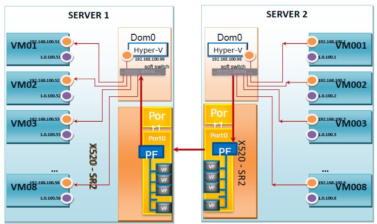
Figure 2 SR-IOV Virtualization Testing Architecture
The comparison of data transmission volumes is shown in Table 2.
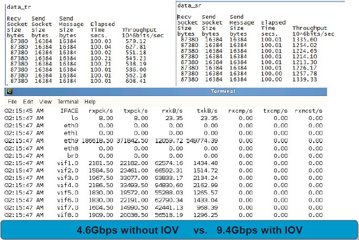
The maximum data volume for ordinary virtualization transmission is 4.6Gbps, while SR-IOV’s direct hardware virtualization can reach 9.4Gbps.
Devices with SR-IOV capabilities also have the following advantages: energy-saving, reduced adapter quantity, simplified cabling, and fewer switch ports. However, SR-IOV has many advantages, but it also has many limitations. For example, many existing features in VMWARE will be unavailable to SR-IOV virtual machines, such as Vmotion, Storage Vmotion, Vshield, NetFlow, High Availability, FT, DRS, DPM, suspend and resume, snapshots, hot-add and remove virtual devices, and joining clustered environments.
Therefore, when considering x86 network virtualization, it is essential to comprehensively consider performance, business characteristics, and infrastructure. If a business requires high performance without needing more flexibility, SR-IOV technology can be considered. Conversely, the common x86 network virtualization technology combined with VMWARE should be chosen for deployment.
Computing Level
From the computing perspective, CPU and memory resources on the x86 physical server can be allocated to virtual machines. Today’s high-performance x86 servers are generally multi-CPU multi-core systems, and the NUMA architecture is becoming increasingly popular because it addresses the challenges of resource allocation between multiple processors, multiple cores, and non-uniform memory architectures, improving the performance of workloads that consume large amounts of memory.
The NUMA architecture is shown in Figure 3.
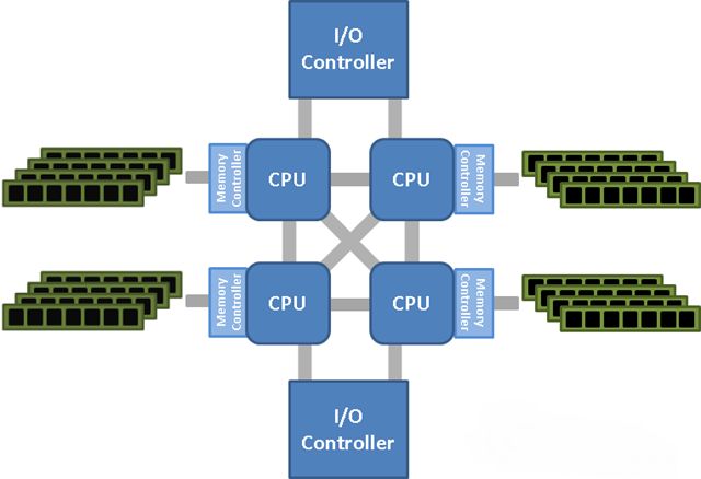
Figure 3 NUMA Architecture Diagram
In traditional server architectures, memory is placed in a single storage pool, which works well for single-processor or single-core systems. However, this traditional unified access method can lead to resource contention and performance issues when multiple cores access the memory space simultaneously. NUMA is a new architecture designed for server CPU and memory, changing how memory is presented to the CPU by partitioning memory for each CPU. Each partition (or memory block) is called a NUMA node, and processors associated with that partition can access NUMA memory more quickly without contending for resources with other NUMA nodes (other memory partitions allocated to other processors). NUMA also allows any processor to access any memory area on the server. A processor can access memory data located in different areas, but it requires more transfers outside the local NUMA node and confirmation from the target NUMA node. This increases overall overhead and affects the performance of the CPU and memory subsystems.
For instance, consider a server configured with two eight-core processors and 128GB of memory. In the NUMA architecture, each processor can control 64GB of physical memory, and each core of the eight cores of each processor corresponds to an 8GB NUMA node. How does this affect VM performance? Since each processor core accesses memory within the NUMA node faster than memory outside it, when the memory size of a virtual machine is less than or equal to the memory size of the NUMA node, the VM can theoretically achieve the best performance. Therefore, when allocating VMs on this physical server, do not allocate more than 8GB of memory to each virtual machine. If more memory is allocated to a VM, it will inevitably need to access memory portions outside its NUMA node, which will affect its performance to some extent. If the application can perceive NUMA, it will be even better. vSphere uses vNUMA to create virtual machines that can perceive NUMA. These VMs will be split into virtual NUMA nodes, with each vNUMA node placed in a different physical NUMA node. Although the VM still spans two NUMA nodes, the operating system and applications within the VM can perceive NUMA, optimizing resource usage.
NUMA has brought many changes to how memory is installed and selected in data center servers. When adding physical memory to a server, we need to ensure that the added memory is balanced and matched across NUMA nodes so that each processor on the motherboard has the same amount of memory. If we configure more memory in the server example provided, we must balance these memory modules between processors. If we add 64GB of memory, each processor will be allocated 32GB of memory (the memory available to each processor will increase to 96GB, and the total memory of the server will reach 192GB), and the memory size of each NUMA node will increase from 8GB to 12GB.
In line with VMware’s best practices, VMware generally advises a maximum of 64 vCPUs for CPUs, typically not exceeding 32, and it is best not to over-provision; memory is generally not advised, as different businesses will have varying requirements for memory size, and it is best not to call across NUMA units. Additionally, it is important to note that the NUMA architecture applies only to physical CPUs (Sockets) and not to cores. Since each socket controls different memory slots, it is essential to ensure that memory slots are evenly distributed. For example, if 128GB of memory is divided into eight 16GB memory sticks, four should be placed in one socket’s memory slots, and the other four in another socket’s memory slots. When allocating vCPU resources to VMs, try to distribute them according to socket/core multiples, such as 1X1, 1X2, 1X4, 1X8, 2X1, 2X2, 2X4, 2X8, etc., but avoid combinations like 2X3, 2X5, or 2X7, as these will cause cross-socket memory calls and can lead to performance degradation.
Storage Level
From the storage perspective, VMs on x86 physical servers connect to LUNs coming from backend storage. There are three ways to create virtual disks on LUNs: thick provision lazy zeroed, thick provision eager zeroed, and thin provisioned. As shown in Figure 4.
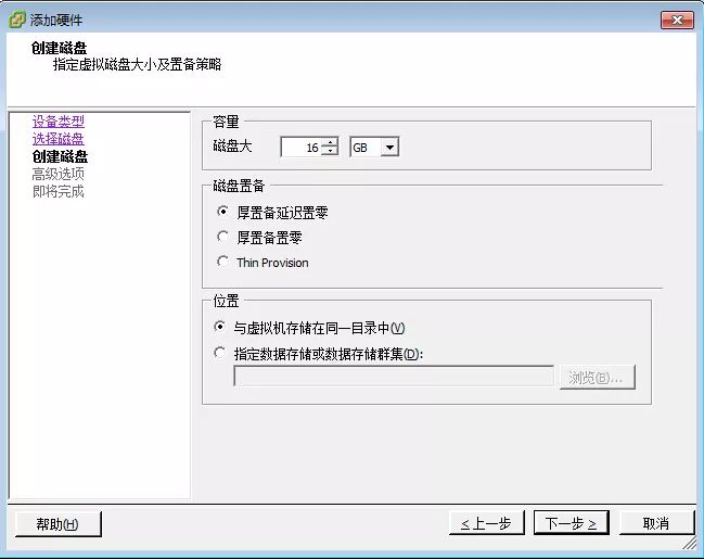
Figure 4 Three Modes of Disks
Thick provision lazy zeroed creates a virtual disk in the default thick format, allocating all required space for the virtual disk during creation. It does not erase any data retained on the physical device during creation, but will zero it out as needed when the virtual machine performs its first write operation. In simple terms, it immediately allocates the specified size of space without clearing the data within that space temporarily, and later clears it as needed; thick provision eager zeroed creates a thick disk that supports cluster features (such as Fault Tolerance). It allocates the required space for the virtual disk during creation. In contrast to the flat format, it zeroes out any retained data on the physical device during creation. Creating this type of disk may take longer than creating other types. In simple terms, it immediately allocates the specified size of space and clears all data within that space; thin provisioned uses a thin provisioning format. Initially, the thin provisioned disk only uses the data storage space required at the beginning. If the thin disk needs more space later, it can grow to its maximum capacity. In simple terms, it specifies the maximum space for the disk file and checks if it exceeds the limit when it needs to grow.
Additionally, the thin provision format may have some negative performance impacts compared to the thick provision format when used by VMs. This is because thin provisioned disks are dynamically expanded, and a multi-GB-sized vmdk file on the disk is not generated all at once, meaning it does not occupy contiguous disk space like thick provisioned disks do. Thus, accessing thin provisioned disks will inevitably lead to longer seek times due to the disk heads moving between non-contiguous disk blocks, affecting Disk I/O performance.
In summary, whether during deployment or application, the performance of thin provisioned formats is inferior to thick provisioned formats, so it is recommended to use thick provisioned virtual disks when space is not tight.
3
Performance Optimization After x86 Virtualization in Relation to Business
For example, a postfix email system under Linux includes an email server, database, and network. From the disk perspective, a significant issue for the email system is not the reading and writing of many large files, but rather the reading and writing of many small files, and these read and write requests come from multiple processes or threads at the same time. For applications that involve many small file read and writes, it is recommended to use the Thin provision mode when allocating the disk for email users. This avoids the large initial space occupation and allows for growth as needed.
From a memory perspective, for postfix, each of its processes does not consume much memory. We expect a large amount of memory to be automatically utilized for disk caching to improve disk I/O rates, and this is something we do not need to operate; Linux takes care of it for us! The virtual memory management in Linux defaults to using all free memory space as disk cache. Therefore, in production Linux systems with several GB of memory, it is common to see only 20MB of available memory. From the processor perspective, neither SMTP nor IMAP significantly occupies the CPU. Therefore, when allocating CPU and memory resources, we can configure them in fixed-size units according to the NUMA architecture. For instance, if a server is configured with two eight-core processors and 128GB of memory, virtualizing into four email servers can allocate 4 cores and 32GB to each.
From a network perspective, the email system frequently uses the network subsystem, but the bottleneck of the email system is still disk throughput rather than network throughput. For applications that do not require strong interaction and allow for latency, the impact of whether the network card is virtual or SR-IOV is minimal.
For the database server of the email system, since there are many small file random reads and writes, the disk for the database can choose the thick provision mode to improve I/O for small data blocks.
For different business systems, specific problems need to be analyzed individually; performance optimization is not a one-time effort. As business develops and changes, the technical means and methods for optimization will also change accordingly.
4
Daily Use and Management of x86 Server Virtualization from an Enterprise Perspective
Different enterprise-level applications have varying utilization rates for CPU, memory resources, and space. How to utilize the NUMA architecture to optimize resource allocation and enhance performance is also very meaningful for managing enterprise data centers.
See Table 3
|
Application |
CPU |
Memory |
IOPS |
Throughput |
|
Database |
High |
High |
140 IOPS |
15MB/S |
|
Email System |
Low |
High |
320 IOPS |
20MB/S |
|
VDI Desktop |
Low |
Low |
15 IOPS |
4MB/S |
|
Website |
Variable |
Variable |
1400 IOPS |
18MB/S |
|
File Server |
Low |
Low |
80 IOPS |
9MB/S |
Table 3 Comparison of Resource Utilization Rates of Different Enterprise Applications
For database servers, due to high requirements for CPU and memory resources, they are not suitable for multi-machine resource sharing. Therefore, it is best to use well-configured physical machines. In contrast, VDI desktops and file servers are more suitable for fixed CPU and memory unit allocation under the NUMA architecture. The email system requires specific NUMA architecture resource allocation based on specific circumstances. For websites with variable demands, not all should be configured as NUMA; for example, cache servers in a website are more suited for non-NUMA architecture memory allocation. When allocating disk space, business systems with high I/O performance requirements are suitable for thick provisioned space allocation, while systems with lower I/O performance requirements and less growth space are suitable for thin provisioned space allocation.
5
Conclusion
x86 server virtualization is a technology used to integrate server resources and improve efficiency. x86 virtualization can lead to higher utilization rates of server hardware and system resources, resulting in a high-reliability server application environment with transparent load balancing, dynamic migration, automatic fault isolation, and system auto-reconstruction, as well as a simpler, unified server resource allocation management model.x86 server virtualization also greatly enhances the overall resource utilization of data centers after resource allocation and aligns with today’s new concepts of green energy efficiency.
Author Introduction:
Sun Jie, Senior Architect at Beijing Zhongyou Ruifei, renowned technical blogger, and technical expert in the domestic cloud technology community.
↓↓ Click “Read Original” 【Join Cloud Technology Community】
Related Articles:
“Who is the soulmate of the central platform? Click here for valuable insights!
Left or right for the enterprise-level container cloud platform implementation?
Enterprise-level PAAS cloud platforms: Several key issues and challenges that cannot be ignored
For more articles, please follow