Today, we will discuss a concept in electronics that is often confused: the resolution of an Analog-to-Digital Converter (ADC) and its accuracy. Although these two terms sound similar, they represent vastly different meanings, much like a ruler where fine markings do not guarantee accurate measurements!
1. Resolution of ADC (Resolution): Similar to the smallest scale on a ruler
Definition: Resolution refers to how many “levels” the ADC can divide the input voltage into. It is like how many smallest markings a ruler has.
Representation: It is usually expressed in bits. For example, a 12-bit ADC means it can output 4096 (which is 2 raised to the power of 12) different digital codes, similar to a ruler with 4096 markings.
Function: It determines the smallest voltage change that the ADC can theoretically detect. For a 12-bit ADC, the full-scale voltage is divided into 4096 parts, so the smallest voltage change it can distinguish is approximately 1/4096 ≈ 0.024%.
Key Points (Important!):
-
Resolution is a design parameter, representing the ideal capability.
-
It only tells you how many divisions the ruler has, but does not guarantee that these divisions are accurate!
-
It does not reflect how large the actual conversion error is. The error is determined by non-ideal factors (such as Integral Non-Linearity (INL), offset).
Resolution = Minimum scale number = Theoretical resolution capability
2. Accuracy (Accuracy): Is the ruler accurate, and does it measure correctly?
Definition: Accuracy refers to how much the digital value output by the ADC differs from the actual analog input value. In simple terms, it is how large the conversion error is.
Representation: In the field of data conversion, accuracy is also often expressed in bits. For example, saying an ADC has “12-bit accuracy usually means its maximum conversion error is less than 1 LSB (Least Significant Bit, which represents the voltage of the smallest scale).
Relationship with Resolution (Core Difficulty!):
- Accuracy can be much lower than resolution! Imagine a ruler with very fine markings (high resolution) but is miscalibrated.
Case 1 (Figure 1): A 12-bit ADC, due to the presence of Integral Non-Linearity error (INL), has an error of 4 LSB for a certain AD output code.
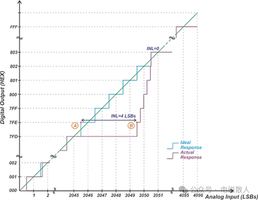
Figure 1: Example of a 12-bit ADC
According to the formula (error value in LSB):
The calculation result is:
12 – log₂(4) = 12 – 2 = 10 bits
This indicates that although it is rated as a 12-bit ruler (fine scale), the actual measurement error level is only equivalent to a 10-bit ruler (coarse but accurate) with a maximum error of 1 LSB. The advantage of low quantization noise brought by high resolution is overwhelmed by large Integral Non-Linearity errors.
-
Accuracy can also be higher than resolution! Imagine a ruler with few markings (low resolution) but extremely precise markings.
Case 2 (Figure 2): A 3-bit ADC (only 8 codes), its maximum INL error is only 0.125 LSB.
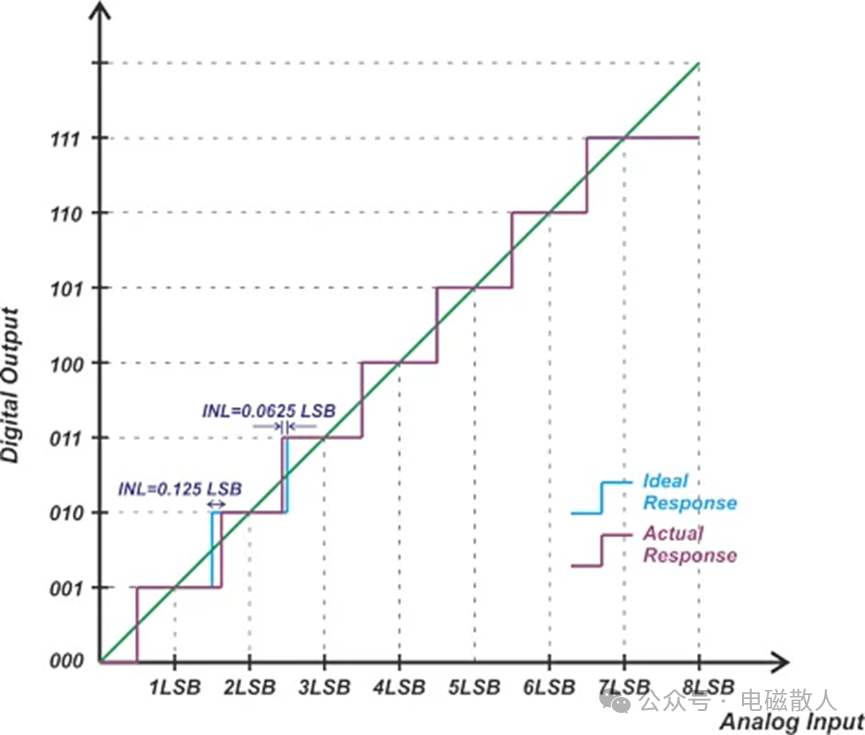 Figure 2: Example of a 3-bit ADC curveUsing the same formula to calculate its accuracy:
3 – log₂(0.125) = 3 – (-3) = 6 bits
Wow! This means that this “coarse” ruler with only 8 markings has a measurement error level equivalent to a 64 marking 6-bit ruler (maximum error 1 LSB)! This indicates that its linearity is very good, and every step is measured accurately.
Accuracy = Actual measurement error level.
Formula: Accuracy (bits) = Resolution (bits) – log₂(Error(LSB)
Both accuracy and resolution can be expressed in bits (bit), but they represent completely different concepts:
-
Resolution (bit): Represents the theoretical quantization capability of the ADC (how many discrete levels it has).
-
Accuracy (bit): Represents the actual performance level of the ADC (how much the conversion error is equivalent to in terms of ideal ADC), and this bit number is calculated based on the actual error.
3. What is the use of accuracy > resolution? The mystery of two-step ADCs
Look at Figures 3 and 4, there is an efficient ADC structure called two-step ADC (also known as Sub-range or Two-step ADC). Its working principle is quite interesting:
1.First Stage – Coarse Quantization (Coarse ADC): Acts like a fast “scout,” quickly determining the approximate range of the input voltage using fewer bits (for example, 3-bit). This will produce a large “quantization error” (also known as residual signal).
2.Second Stage – Fine Quantization (Fine ADC): Acts like a precise “measurer,” specifically responsible for measuring the residual signal left by the first stage (the low bitsLSB).
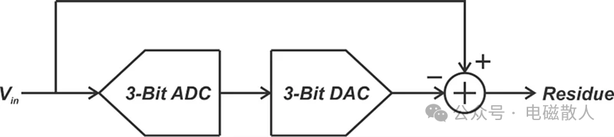
Figure 3: Diagram of the “residual” signal obtained by subtracting the DAC output signal from the ADC input signal
The key point is here!
The accuracy of the first stage “scout” (Coarse ADC) must be very high (far exceeding its resolution)!
Why? Because if the first stage generates a large error (non-linearity) when determining the large range, then the residual signal it produces is itself distorted. No matter how good the second stage is, it will also measure incorrect things, and the final result will definitely be inaccurate.
Similarly, the DAC that converts the digital result of the first stage back to analog voltage, and the subtractor circuit, must also have very high accuracy; otherwise, the residual signal will also be erroneous.
Expanding the concept of Figure 3, we can obtain the complete system structure in Figure 4:
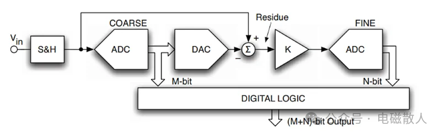
Figure 4: System block diagram of Sub-range or Two-step ADC
The advantages of this ADC circuit structure: This structure can achieve high resolution with far fewer comparators than a full flash ADC (for example, a 12-bit ADC only requires a few dozen comparators in two stages, rather than 4096 comparators), saving area, power consumption, and speed (relative to successive approximation types). However, the prerequisite is that the first stage and related circuits must be “precisely calibrated” (high accuracy)!
4. How to comprehensively evaluate accuracy? Using “Total Unadjusted Error (TUE)”
The actual errors of the ADC come from many sources: zero point inaccuracies (Offset Error), gain inaccuracies (Gain Error), and Integral Non-Linearity errors (INL). How can we look at the overall accuracy? Engineers often use an indicator:Total Unadjusted Error (TUE).
The calculation formula is (units are usually in LSB):

Calculation example: A 12-bit ADC: Offset Error = 2.5 LSB, Gain Error = 3 LSB, INL = 3 LSB, then:
TUE = √(2.5² + 3² + 3²) = √(6.25 + 9 + 9) = √24.25 ≈ 4.92 LSB
Then using the core formula for accuracy calculation mentioned above:
Accuracy = 12 – log₂(4.92) ≈ 12 – 2.3 ≈ 9.7 bits
This indicates that considering all major errors, this nominal 12-bit ADC has an actual accuracy of about 9.7 bits.
The role of calibration: We can eliminate the Offset and Gain Error through calibration circuits or software algorithms (adjusting them close to zero). Thus, the remaining major error is the INL, which becomes the bottleneck for accuracy. High-accuracy ADC design must tackle the INL!
5. Important Reminder: System-Level Thinking
-
ADC is not the only source of error! Remember that the input buffer (Input Driver) providing the signal to the ADC, the voltage source providing the reference voltage (Voltage Reference), and other peripheral circuits will also introduce additional errors. When designing high-accuracy systems, the entire signal chain needs to be optimized.
-
Calibration is key: To achieve optimal performance, calibrating the Offset and Gain is almost essential, so that the INL “hard nut” can be exposed and resolved.
6. Summary: The Dialectical Relationship Between Resolution and Accuracy
By now, we have thoroughly clarified:
-
Resolution (Resolution): is the theoretical capability, representing “how fine the smallest scale of the ruler is.” It determines the size of quantization noise (the finer the scale, the smaller the rounding error).
-
Accuracy (Accuracy): is the actual performance, representing “how accurate the ruler is and how well it measures.” It is mainly determined by non-ideal factors such as Integral Non-Linearity Error (INL).
-
Relationship between the two: They can change independently! High resolution does not equal high accuracy (Case 1), and low resolution can also achieve high accuracy (Case 2).
-
Design Insights:
Pursuing high resolution? Mainly to reduce quantization noise.
Pursuing high accuracy? The core is to suppress Integral Non-Linearity Error (INL), especially in multi-stage ADC (such as two-step ADC), where the accuracy of the first stage is crucial.
-
Evaluation Tool: Use TUE to comprehensively evaluate the total error of the ADC and extend it to assess the performance of the entire signal chain.
Next time you see the bit count (resolution) of an ADC, be sure to ask: what is its accuracy (especially the INL)? Don’t be fooled by the “high resolution” label! Just like buying a ruler, you cannot just look at how dense the markings are; the key is whether the markings are accurate!
(Original source: https://www.allaboutcircuits.com/technical-articles/adc-resolution-vs-adc-accuracy-subrange-adc-two-step-adc-and-total-unadjusted-error/)