Table of Contents | 2023 Issue 2 Special Topic: Key Technologies of 6G and Their Applications
Intelligent 6G: Edge Deployment and Lightweight Networking
Online Path Planning Method for Cellular Connected Drones Based on Map Reconstruction
Two-dimensional Fast Direction Finding Algorithm for Millimeter-wave Large-scale Polarization-sensitive Arrays
Identification of Specific Radiation Sources Based on Signal Feature Knowledge Graph and Width Learning Architecture
Denoising Autoencoders for Spectrum Sensing Adversarial Defense Models
Modulation Recognition Model Based on CNN-GRU and CA-VGG Feature Fusion
Research on User Equipment RF Fingerprinting Technology Based on Device-level Simulation
Exploration of Key Technologies for 6G Multi-carrier Multi-modal Fusion Networking
Drone Beam Tracking Based on Location and Attitude Prediction
Emergency Assurance Scheme for Government-enterprise Dedicated Lines Based on 5G Network and SD-WAN Technology
Research and Implementation of Real-time Stitching Technology of Panoramic Video
Liu Tai, Hu Bin, Tian Jinlong, Ren Weijia, Gao Chao
(Wuhan Zhongyuan Electronics Group Co., Ltd., Wuhan, Hubei 430205)
AbstractWith the continuous development of the unmanned field, operators of drones, unmanned vehicles, and automotive assisted driving need to operate through seamless panoramic video, otherwise they cannot grasp the complete visual situation of unmanned devices. By using the TP2854 video data conversion chip, multi-channel analog video data captured by AHD cameras is converted into digital signals for the processor, and then the SURF algorithm and FLANN algorithm are used for feature point detection and vector calculation, image matching, homography matrix calculation, and image fusion, ultimately encoding and streaming the fused image data to achieve panoramic video stitching. The focus is on continuously improving the image fusion algorithm to achieve seamless and shadow-free panoramic images.
KeywordsVideo Acquisition; Image Matching; Image Fusion; Panoramic Stitching
doi:10.3969/j.issn.1006-1010.20220331-0001
Classification Number: TN92 Document Code: A
Article Number: 1006-1010(2023)02-0068-09
Citation Format: Liu Tai, Hu Bin, Tian Jinlong, et al. Research and Implementation of Real-time Stitching Technology of Panoramic Video[J]. Mobile Communications, 2023,47(2): 68-76.
LIU Tai, HU Bin, TIAN Jinlong, et al. Research and Implementation of Real-time Stitching Technology of Panoramic Video[J]. Mobile Communications, 2023,47(2): 68-76.

0 Introduction
The panoramic video stitching system utilizes multiple fixed cameras to capture the same scene from different angles, generating images with a wider field of view than a single image through video image stitching technology based on the correlation between images. This technology is increasingly applied not only in military unmanned fields but also plays a vital role in automotive assisted driving systems. As the number of motor vehicles rapidly increases, the development of urban traffic systems lags behind, leading to a sharp deterioration in urban traffic conditions and a yearly increase in traffic accidents[1]. For car owners driving in large cities, a significant portion of traffic accidents is caused by the visual blind spots of vehicles, making it difficult for drivers to accurately judge the distance between vehicles[2]. In recent years, with the continuous improvement of video coding technology and the performance of onboard equipment, providing bird’s-eye panoramic video functionality in assisted driving systems has become a common demand among car owners and a hot topic in the current development of assisted driving systems[3].
This paper uses the Allwinner T5 core board, capturing multi-channel analog camera image data with the TP2854 video acquisition chip, and studies multi-channel panoramic video stitching technology using feature extraction-based registration algorithms and the OpenCV library.
Video streams consist of multiple images; for 25 frames of video, 1 second of video contains 25 images. Therefore, image stitching technology is the foundation of video stitching. Compared with image stitching technology, the focus of video stitching is on accuracy and real-time performance. This paper studies some basic principles and improvement methods in the image stitching process, mainly focusing on feature extraction and image fusion. The core technologies of video stitching are video image registration and fusion, where this paper uses the SURF feature point extraction as the feature extraction algorithm, and based on the extracted image feature points, utilizes the FLANN algorithm for feature registration, followed by the calculation of the perspective transformation matrix between images.
The key and challenging aspect of this paper is image fusion. If the overlapping areas of images after perspective transformation are not processed well or not processed at all, shadows or seams will appear in the overlapping areas. This paper employs a weighted averaging method to handle the overlapping areas of images and improves the algorithm to further enhance its practicality.
To address the real-time nature of video stitching, this paper proposes the idea of collecting video from fixed camera positions, placing feature point matching and homography matrix calculations in the startup program, so that each time the captured image data only undergoes image transformation and fusion, achieving real-time video stitching.
1 System Hardware Composition
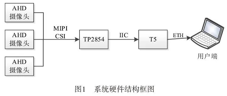
The system hardware mainly consists of three parts: Allwinner T5, TP5854 acquisition chip, and AHD camera. The system operation process is as follows: using AHD cameras to capture image analog data, converting the image analog data into digital signals through TP2854, obtaining data through IIC on T5, performing image stitching algorithms, and finally encoding and streaming the panoramic image data to the user end. The system block diagram is shown in Figure 1:
The Allwinner T5 series is a high-performance quad-core Cortex-A53 processor suitable for the new generation automotive market. The T5 series meets the automotive AEC-Q100 testing requirements. This chip integrates a quad-core Cortex-A53 CPU, G31 MP2 GPU, multiple video output interfaces (RGB/2*LVDS/HDMI/CVBS OUT), and multiple video input interfaces (MIPI CSI/BT656/BT1120). The GPU supports OpenGL ES 1.0/2.0/3.2, Vulkan 1.1, and OpenCL 2.0, which can accelerate the execution time of algorithms when processing video data.
Additionally, the T5 chip supports 4K@60fps H.265 decoding and 4K@25fps H.264 decoding, DI, 3D noise reduction, an automatic color adjustment system, and a trapezoidal correction module that can provide a smooth user experience and professional visual effects.
2 Video Stitching Principle Analysis
The basic process of the system software is to capture video through multiple AHD HD cameras, stitch it, encode it, and send it to the user end via RTSP streaming.
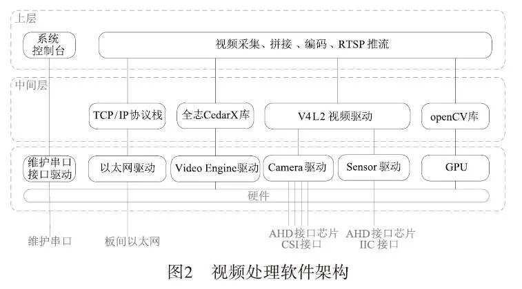
The video processing software mainly consists of upper-level software, middle-layer software, and lower-layer software, with its layered architecture shown in Figure 2. The video acquisition module uses the V4L2 video driver framework for acquisition, the video stitching module uses the OpenCV library for multi-channel video stitching, the video encoding module uses the Allwinner CedarX library for encoding, and the video streaming module uses the RTSP protocol for streaming. The software architecture for video processing is shown in Figure 2:
2.1 V4L2 Video Driver Module
V4L2 (Video for Linux 2) is the standard video acquisition driver framework for Linux, located in the Linux kernel state. It consists of a hardware-independent V4L2 driver core and hardware-related Camera drivers, Sensor drivers, etc. The V4L2 driver core is responsible for the registration and management of specific camera drivers, providing a unified device file system interface for Linux user-space applications to read camera data and control camera parameters; the Camera driver is the camera driver related to specific hardware platforms for video frame processing; the Sensor driver is the camera-related sensor driver that controls camera parameters. For the video processing module, the Sensor driver is the driver for NVP6324.
The video acquisition module is based on the V4L2 video driver, and the acquisition process is shown in Figure 3:
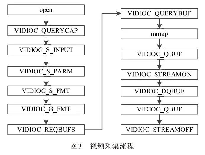
The basic steps are as follows:
(1) Open the video device file;
(2) Query the capabilities of the video device, such as whether it has video input or audio input/output, etc.
(3) Set the parameters for video acquisition.
Set the video standard, which includes PAL/NTSC.
Set the size of the video image acquisition window.
a) Set the video frame format, including the pixel format, width, and height;
b) Set the video frame rate;
c) Set the video rotation mode.
(4) Request/allocate frame buffers for video stream data from the driver.
Request/allocate several frame buffers, generally no less than three. Query the length and offset of the frame buffers in kernel space.
(5) The application maps the addresses of the frame buffers to user space through memory mapping, allowing direct manipulation of captured frames without copying.
(6) Place all allocated frame buffers into the video acquisition output queue to store captured data.
(7) Start the acquisition of video stream data.
(8) The driver stores one frame of captured video data in the first frame buffer of the input queue, and after storing, moves this frame buffer to the video acquisition output queue.
(9) The application retrieves the frame buffer containing the captured data from the video acquisition output queue and processes the raw video data of this frame buffer.
(10) After processing, the application requeues this frame buffer into the input queue to allow continuous data acquisition.
Repeat steps 8 to 10 until data acquisition is stopped.
(11) Stop video acquisition.
(12) Release the allocated video frame buffers and close the video device file.
2.2 Real-time Video Stitching Process
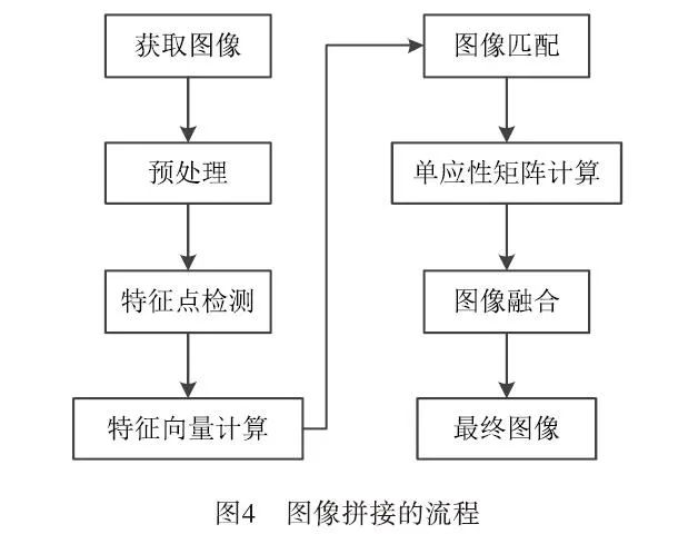
Video stitching is developed based on image stitching, so image stitching is the core step of video stitching, and the result of image stitching directly affects the result of video stitching. In recent years, there have been many methods for image stitching, but the general steps can be divided into: image preprocessing, image registration, and image fusion. Among them, image registration and image fusion are the difficult issues in image stitching research. The specific steps of image stitching are shown in Figure 4:
The principle of video stitching is to first extract frames from video information, then perform feature extraction, matching, and fusion on the extracted frame images according to the steps of image stitching, and finally compress the completed stitched frame images back into video information, thus completing the video stitching task. The basic flowchart of video stitching is shown in Figure 5:
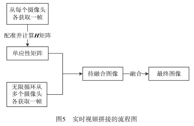
To ensure the real-time and accuracy of video stitching, compared to common video stitching methods, the final adopted video stitching method is as follows:
(1) Only capture suitable images from multiple video images and save them.
(2) Perform registration operations based on the images from the first step.
(3) Calculate the homography matrix between the images of the four cameras and store it in a Mat.
(4) For the remaining video frames that need real-time stitching, directly call the homography matrix stored in Mat to simplify the registration process.
Thus, the remaining video frames that require real-time stitching can save the time of feature extraction and registration each time, only needing to perform image transformation stitching and image fusion using the perspective transformation matrix. Meanwhile, this experiment adopts ordinary everyday cameras to complete the video synchronization acquisition process, which not only improves computational efficiency but also enhances the practicality of the research.
2.3 Implementation of Video Stitching Technology
(1) Camera Structure
The camera used is an infrared high-definition night vision video module (hereinafter referred to as the HD video module), with a 6 mm lens and a field of view of 60°, supporting H264, MJPEG, and YUY2 encoding methods, providing excellent indoor and outdoor performance with realistic colors. The HD video module includes infrared light detection circuitry and supports external infrared light boards. It also supports the UVC protocol, with MJPEG and YUY2 being plug-and-play without drivers. The structure uses three cameras as shown in Figure 6:
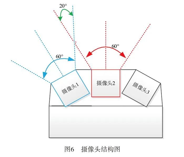
Figure 6 uses three cameras as the image acquisition devices for stitching. The stitching principle for two images is to extract similar feature points from the two images and then perform the stitching process. Before this, it is necessary to find the overlapping area of the two images, where the stitching effect will be better when the overlapping area reaches 30% or more.
When the camera’s field of view is 60°, the stitching effect will be better when the overlapping angle of the two cameras is 20°, as indicated by the intersection of the red dashed line and the blue dashed line in Figure 6.
2.4 Calculation of Image Homography Matrix
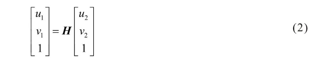
Homography is a concept in projective geometry, also known as projective transformation. It maps points on one projective plane (three-dimensional homogeneous vector) to another projective plane. Homography is a linear transformation of three-dimensional homogeneous vectors and can be represented by a 3×3 non-singular matrix H, which is called the homography matrix. Using this matrix, a point on the projective plane can be projected onto another plane (as shown in Figure 7 where m is projected to m`).
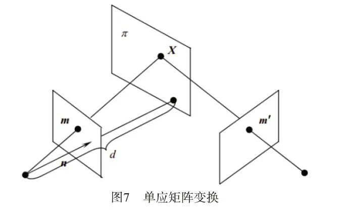
Linear Transformation:

The points on the plane are three-dimensional homogeneous vectors, namely:
Calculating the homography matrix requires preprocessing of two images, image registration, and other operations, specifically as follows:
(1) Image Preprocessing
Preprocessing is an important step in the image stitching process. Due to different image acquisition environments, such as varying light conditions and the performance of related equipment, input images often have noise, insufficient contrast, and other drawbacks. Additionally, distance and focal length can lead to various strange issues in images. To ensure the accuracy and efficiency of feature point extraction and matching, it is essential to preprocess the images. Common image preprocessing techniques include grayscale processing and filtering.
Grayscale Processing: The feature points in images are independent of whether the image is colored or grayscale. Thus, to speed up the registration and fusion process, it is beneficial to convert the color images captured by the camera into grayscale images before performing operations.
Filtering: The images captured by the camera can be subject to various noise interferences during imaging, digitization, and transmission, leading to unexpected degradation in image quality that severely affects the overall visual effect. Typically, these noise interferences cause image degradation, resulting in blurriness and feature drowning, making it difficult to analyze the images. Therefore, it is crucial to suppress various interference signals that degrade image quality, enhance useful signals in the images, and correct different observed images under the same constraints. Common filtering methods include smoothing filtering, median filtering, and Gaussian filtering, each with its own advantages and disadvantages, and different filtering methods should be chosen based on the type of noise.
Since this paper uses the OpenCV library for image processing, the cvtColor function can be utilized for grayscale processing, which is simple and convenient.
(2) Feature Point Detection and Feature Vector Calculation
This paper employs the SURF (Speed Up Robust Feature) algorithm, which is built into OpenCV, for feature extraction. The main five steps of the SURF feature extraction algorithm are: constructing the Hessian matrix, creating a Gaussian pyramid scale space, utilizing non-maximum suppression to preliminarily determine feature points, accurately locating extreme points, selecting the main direction of feature points, and constructing SURF feature point descriptors[4]. The SURF algorithm consists of five steps:
1) Construct the Hessian matrix and Gaussian pyramid scale space.
SURF uses the approximate value image generated by the determinant of the Hessian matrix, which is computationally convenient and has a high detection speed. Assuming the function f(z,y), the Hessian matrix H is composed of the function’s partial derivatives. The Hessian matrix at a certain pixel point in the image is as shown in Equation (3):
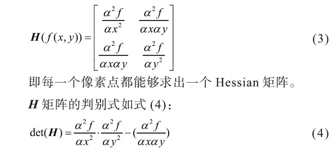
The value of the determinant indicates the eigenvalues of the H matrix, and all points can be classified based on the sign of the determinant. From higher mathematics, to determine whether a point is an extreme point, it is necessary to check whether the value of the determinant is positive or negative.
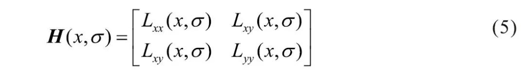
In the SURF algorithm, the image pixel l(x,y) represents the function value f(x,y), and a second-order standard Gaussian function is selected as the filter. The second-order partial derivatives are calculated through convolution with a specific kernel, thus obtaining the three matrix elements Lxx, Lxy, and Lyy of the Hessian matrix, as shown in Equation (5):
However, feature points must possess scale invariance, so Gaussian filtering must be performed before constructing the Hessian matrix. After Gaussian filtering, the Hessian matrix can be computed, as shown in Equation (6):

L(x,t) represents an image at different resolutions, which can be achieved by convolving the Gaussian kernel G(t) with the image function I(x) at point x, where the Gaussian kernel G(t) is shown in Equation (7):
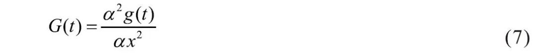
Where t is the Gaussian variance, and g(x) is the Gaussian function. Using this method, the determinant value of the H matrix can be calculated for each pixel in the image, and this value is used to identify feature points. For convenience, Herbert Bay proposed using approximate values instead of L(x,t). The introduction of weights balances the errors between accurate values and approximate values, and the weights change with scale, allowing the determinant of the H matrix to be expressed as Equation (8):
2) Utilize non-maximum suppression to preliminarily identify feature points.
Each processed pixel point is compared with 26 neighboring points in a 3D neighborhood; if it is the maximum or minimum of these 26 points, it is retained as a preliminary feature point.
3) Accurately locate extreme points.
A 3D linear interpolation method is used to obtain sub-pixel level feature points while removing points with values below a certain threshold, increasing the extremity so that only a few of the strongest feature points are detected.
4) Select the main direction of feature points.
The Haar wavelet features in the neighborhood of feature points are statistically analyzed. In the neighborhood of the feature point, the horizontal Haar wavelet features and vertical Haar wavelet features are summed within a 60° sector. The size of the Haar wavelet is adjusted to 4s, resulting in a value for this sector. The 60° sector is rotated at certain intervals, and the direction of the sector with the maximum value is taken as the main direction of the feature point.
5) Construct the SURF feature point descriptor.
In SURF, a square frame is taken around the feature point, with a side length of 20s (s is the scale at which the feature point is detected). This frame is directional, with the direction being the main direction detected in step 4. The frame is divided into 16 sub-regions, and the horizontal and vertical Haar wavelet features of 25 pixels in each sub-region are counted, where the horizontal and vertical directions are relative to the main direction. This Haar wavelet feature consists of the sum of horizontal values, the absolute sum of horizontal values, the sum of vertical values, and the absolute sum of vertical values.
This means that each small region has four values, resulting in each feature point being represented as a 64-dimensional vector, which is half the dimensionality compared to the SIFT algorithm[5]. This advantage becomes particularly evident during feature matching, significantly speeding up the matching process.
(3) FLANN Feature Matching
FLANN stands for Fast Library for Approximate Nearest Neighbors. In high-dimensional space, this search library is commonly used for fast approximate nearest neighbor searches, containing a set of algorithms for performing nearest neighbor searches on datasets and automatically selecting the best algorithm and parameters for the system.
For a high-dimensional feature, it is found that in computer vision, the computational cost of finding the nearest matching points in the data to match is expensive. FLANN feature matching is more efficient and faster than general matching algorithms for high-dimensional features.
After extracting feature points using the SURF algorithm, the feature vectors, or feature descriptors, are calculated and matched using the FLANN matcher. Based on the principles of image transformation, the results of the matched set are computed to derive the transformation matrix, namely the homography matrix.
2.5 Image Fusion
The purpose of image fusion is to seamlessly stitch two images onto the same plane[6].
(1) Direct Averaging Method
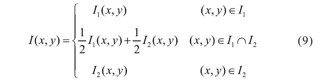
After determining the homography matrix, the object image is transformed onto the target scene using OpenCV functions. The coordinates of the four corners of the overlapping area are computed, which defines the boundary of the overlapping area. In this overlapping area, the corresponding pixel values are set to the average of the pixels from the scene image and the transformed object image, which is known as the direct averaging method. Let I represent the final stitched image, and I1 and I2 represent the images to be stitched, then the relationship is as follows (9):

(2) Weighted Averaging Method
Similar to the direct averaging method, in the overlapping area of the images, the corresponding pixel values are no longer simply set to the average of the scene image and the transformed object image but are weighted before averaging[7-10]. Let I be the final fused image, and I1 and I2 represent the images to be stitched, then the relationship is as follows (10):
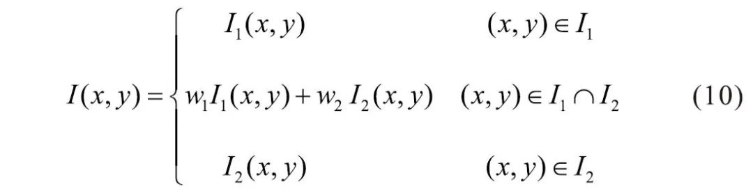
In Equation (10), w1 represents the weight corresponding to the pixels belonging to the left target scene in the overlapping area of the images to be stitched, and w2 represents the weight corresponding to the pixels of the transformed object image in the overlapping area, with w1 + w2 = 1, where 0 < w1 < 1, 0 < w2 < 1. To achieve a smooth transition in the overlapping area, appropriate weights can be selected, effectively eliminating seams at the source.
Based on the actual fusion effect, different weight distribution functions w1 and w2 can be selected. The most commonly used weighted averaging method is the fade-in and fade-out weighted averaging method[11-15]. The two weights are determined by the width of the overlapping area; assuming w1 = 1/width, then in the overlapping area, w1 starts from 1 and gradually decreases to 0, while w2 starts from 0 and gradually increases to 1, ultimately achieving a smooth transition in the overlapping area between I1 and I2.
Additionally, when the pixel values of I1(x,y) or I2(x,y) are too low, the image appears black. That is, when using the fade-in and fade-out weighted averaging method, it is advisable to first check whether the pixel values to be processed are too low; if I1(x,y) < K, then the value of that point is directly discarded, setting w1 = 0, where the K value can be adjusted based on experimental conditions.
3 Experimental Results Analysis
3.1 Experimental Process of Panoramic Stitching
According to the real-time video stitching process, a program was written and cross-compiled using the T5 compiler in an Ubuntu virtual machine. The executable file was then downloaded to the T5 experimental board. Additionally, the necessary library files for the program to run were downloaded to the T5 experimental board directory /usr/bin, allowing the program to run. Below is the image processing process during the program execution:
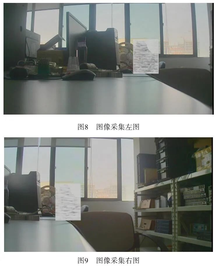
(1) Camera Captures Image
The images captured by the camera are transmitted to T5 via V4l2, and the OpenCV library files are used to obtain the images,as shown in Figures 8 and 9:
(2) Projection Transformation
The two images are projected onto the same plane using the computed homography matrix,as shown in Figure 10:
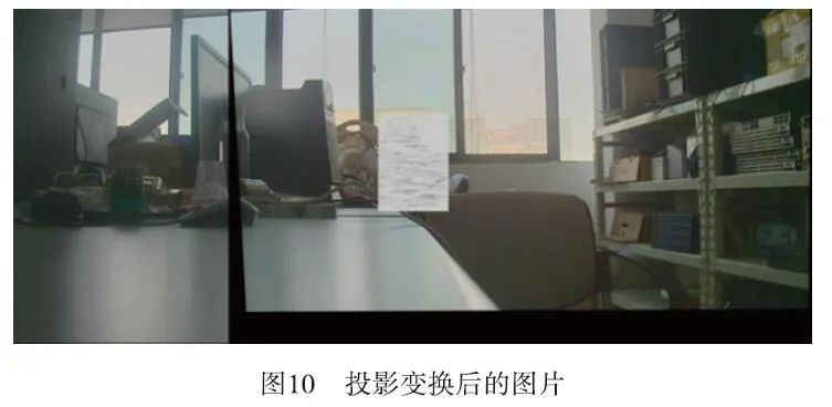
Figure 10 shows the right image projected, and then the left image is pasted onto the plane transformed from the right image.
(3) Image Fusion
Using the fade-in and fade-out weighted averaging method, the two images are fused, resulting in the fused imageas shown in Figure 11.
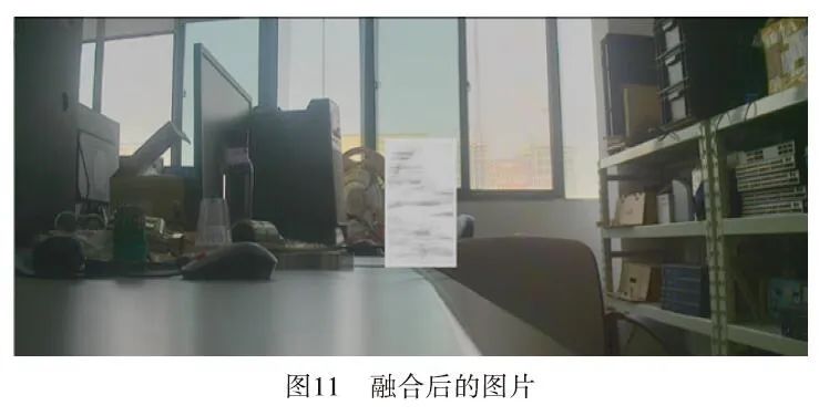
Figure 11 shows the fused image after cropping the excess black areas from the right image after projection transformation, showcasing the perfectly fused image.
3.2 Video Stitching
Video stitching is developed based on image stitching[16-20]. The above demonstrates the entire process of image stitching; the video stitching program only needs to continuously acquire image data from the camera using OpenCV, process the image stitching through algorithmic components, encode it, and stream it for display to the user.
3.3 Comparison of Image Fusion Algorithms
The most critical part of this paper is image fusion. During the experiments, the differences between the results using the improved weighted averaging algorithm and those without this algorithm were significant, as demonstrated in the following experiments:
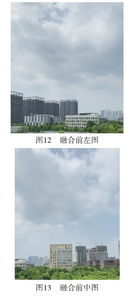
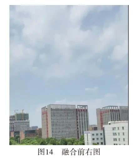
(1) Captured Images
The three captured imagesare shown in Figures 12, 13, and 14:
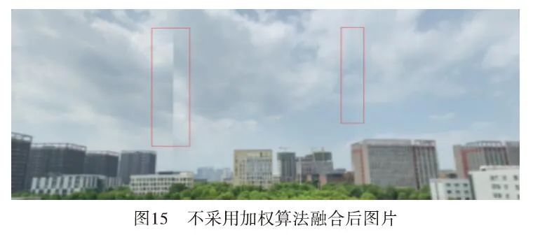
(2) Image Fusion Without Weighted Averaging Algorithm
The image fused without the weighted averaging algorithmis shown in Figure 15:
(3) Image Fusion Using Weighted Averaging Algorithm
After applying the improved weighted averaging algorithm, the stitched imageis shown in Figure 16:
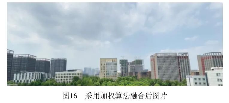
After using the weighted averaging algorithm, the seams in the stitching are nearly invisible, and the visual effect is good, demonstrating excellent practicality.
4 Conclusion
This paper implements real-time stitching of multiple videos using the Allwinner T5 platform. After capturing data from multiple cameras, the OpenCV algorithm is used to process the data. Through feature point extraction, homography matrix calculation, perspective transformation, and fusion processing, wide-view images or panoramic images are generated. Improvements in the image fusion algorithm have enhanced the fusion effect. However, a limitation of this research is the slightly larger delay during video stitching, which may slightly affect the viewing experience. Future work will further optimize the video stitching design on the Allwinner T5 platform.
References:(Scroll Up and Down to Browse)
[1] BURDEA C, COIFFET P .Virtual reality technology[M]. Beijing: Electronics Industry Press, 2003.
[2] Ishibuchi H, Tsukamoto N, Nojima Y. Diversity Improvement by Non-geometric Binary Crossover in Evolutionary Multiobjective Optimization[J]. IEEE Transactions on Evolutionary Computation, 2010,14(6): 985-998.
[3] T POGGIO, V TORRE. III—posed problems and regularization analysis in nearly Vision[Z]. Artificial Intelligence Lab, Memo, No. 773, Massachusetts Institute of Technology, 2014: 56-68.
[4] Wu Jian, Lan Shiyong, Huang Feihu. Design and Implementation of a Multi-channel Fast Video Stitching System[J]. Computer Engineering, 2014(2): 208-216.
[5] Ming Anlong. Target Matching Based on Regional SIFT Descriptors Between Multi-cameras[J]. Journal of Computer Science, 2008.
[6] Wang Mao. Research and Design of Visual Fusion for Large Scene Based on FPGA[D]. Chengdu: University of Electronic Science and Technology of China, 2014.
[7] Sun Mingwu, Mao Yimeng. Comparison and Application Discussion of Three Image Fusion Algorithms[J]. Journal of Shanxi Datong University (Natural Science Edition), 2021,37(4): 29-32+106.
[8] Zhu Wang, Shen Jianghai. An Improved Algorithm for Seamless Stitching of Core Images[J]. Computer Knowledge and Technology, 2021,17(26): 105-107.
[9] Zhu Lingyun, Zheng Zhitian. Image Stitching Algorithm Based on Saliency Weight Fusion[J]. Electronic Production, 2019(24): 49-50.
[10] Liu Yusong. Research and Implementation of Image Stitching Technology for Drones[D]. Hefei: Anhui University, 2018.
[11] Balcerek J, Konieczka A, Marciniak T, et al. Video processing approach for supporting pedestrians in vehicle detection[C]//2014 Signal Processing: Algorithms, Architectures, Arrangements, and Applications (SPA). 2014: 100-103.
[12] Ramesh I, Sivakumar I, Ramesh K, et al. Categorization of YouTube Videos by Video Sampling and Keyword Processing[C]//2020 International Conference on Communication and Signal Processing (ICCSP). 2020: 56-60.
[13] Ghadiyaram D, Pan J, Bovik A C. A Subjective and Objective Study of Stalling Events in Mobile Streaming Videos[C]//IEEE Transactions on Circuits and Systems for Video Technology. IEEE, 2019,29(1): 183-197.
[14] Zhou H, Jayender J. Real-Time Nonrigid Mosaicking of Laparoscopy Images[C]//IEEE Transactions on Medical Imaging. IEEE, 2021,40(6): 1726-1736.
[15] Imanuel I, Lee S. Image Compression with Channel-wise Decoder[C]//2022 IEEE International Conference on Consumer Electronics-Asia (ICCE-Asia). IEEE, 2022: 1-3.
[16] Fang Z, Yu X, Pan J, et al. A Fast Image Mosaicking Method Based on Iteratively Minimizing Cloud Coverage Areas[C]//IEEE Geoscience and Remote Sensing Letters. IEEE, 2021,18(8): 1371-1375.
[17] Shang Z, Ebenezer J P, Wu Y, et al. Study of the Subjective and Objective Quality of High Motion Live Streaming Videos[C]//IEEE Transactions on Image Processing. IEEE, 2022,31: 1027-1041.
[18] Huang S, Luo Z, Xu J, et al. Perceptual Evaluation of Pre-processing for Video Transcoding[C]//2021 International Conference on Visual Communications and Image Processing (VCIP). 2021: 1-5.
[19] Rasch J. A Signal Adaptive Diffusion Filter For Video Coding[C]//2018 Picture Coding Symposium (PCS). 2018: 131-133.
[20] Kulkarni V, Talele K. Video Analytics for Face Detection and Tracking[C]//2020 2nd International Conference on Advances in Computing, Communication Control and Networking (ICACCCN). 2020: 962-965. ★