Overview
The surround view system utilizes four wide-angle fisheye cameras around the vehicle, typically installed at the front, rear, and below the side mirrors, to create a 360-degree blind spot-free coverage around the vehicle. The surround view system provides a panoramic parking video assistance and integrates multiple warning functions, becoming an important component in the mainstream ADAS market. In the composition of sensors for autonomous driving, surround view sensors are also an essential part due to their blind spot-free coverage around the vehicle.
System Architecture
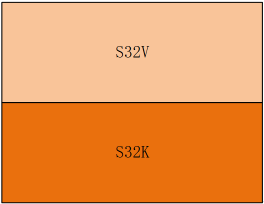
The S32V is primarily responsible for graphics and image processing, enabling the 360-degree surround view functionality. The S32V communicates with the S32K system via a UART interface. The S32K serves as the master control unit, coordinating the work of all system components and communicating with the vehicle.
System Simplified Diagram
The S32V processor: This chip is NXP’s second-generation vision processor series, designed to support compute-intensive applications for image processing, and provides an ISP, a powerful 3D GPU, dual APEX-2 vision accelerators, and security, supporting SafeAssure™. The S32V is suitable for ADAS, NCAP front-view cameras, foreign object detection and recognition, surround view, machine learning, and sensor fusion applications. The S32V is designed for automotive-grade reliability, functional safety, and security measures to support automotive and industrial automation.。
Computing Unit and Surround View Camera Interface
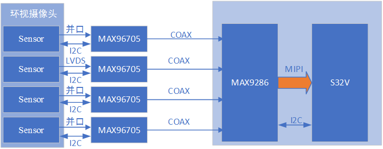
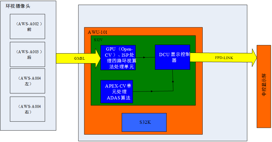
The video signal from the surround view cameras is accessed through a parallel signal converted to MIPI into a serializer, while coaxial signals are deserialized by the MAX9286 and then accessed to the S32V processor via MIPI interface. The S32V processes the data internally (using GPU or ISP) and then sends the stitched video signal to the S32V display controller via its internal bus.
S32V Camera Unit Driver: The cameras are connected to the S32V’s MipiCsi interface through a serializer/deserializer chip. I2C is responsible for camera initialization and provides a user-space API interface for reading and writing sensor registers in user space. Various types of camera sensors can be configured and controlled through the user-space I2C API.
The camera driver architecture is divided into three layers. The first layer operates in kernel space, implementing basic communication for I2C devices; the second layer operates in user space, implementing camera configuration; the third layer completes most of the driver’s functions.
S32V Display Unit Driver
Video and Data Stream Interface: Utilizing the S32V DCU controller combined with the FPDLINK serial deserializer chip, the surround view video data is output to the display, providing the driver with a 360-degree blind spot-free view, thereby enhancing driving safety.
Surround View Imaging System Software Design Process
Surround View Imaging Design Process
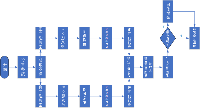
The surround view imaging system software is mainly divided into three parts: perspective transformation, panoramic view stitching, and image enhancement. The system software process is shown in the figure above. First, initialize the system parameters, setting the horizontal and vertical angles of the cameras, installation angles, and installation heights; then acquire images from around the vehicle, dividing them into two groups: perspective images for the front and rear of the vehicle and top-down images for the left and right sides; using the image inverse projection transformation algorithm based on the set parameters to convert the perspective images from the front and rear of the vehicle into top-down bird’s-eye views; after converting all images around the vehicle into top-down views, calibrate the stitching points in the overlapping areas of adjacent cameras; determine the stitching point positions in the two images to be stitched and thus determine the seams of the two images; generate a panoramic image stitching mapping table based on the parameters for stitching each pair of images, allowing the system hardware to complete the stitching and generate a panoramic image around the vehicle; finally, the driver can choose whether to enhance the panoramic image based on the brightness conditions around the vehicle, outputting the enhanced panoramic bird’s-eye video image.
Algorithm Description of the Surround View Imaging System
The surround view imaging system mainly consists of camera intrinsic parameter calibration algorithms, camera extrinsic parameter calibration algorithms, and surround view synthesis algorithms. Each algorithm module can be further divided into several sub-modules.
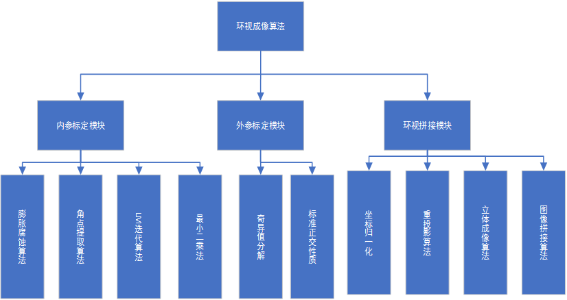
Algorithm Composition of the Surround View Imaging System
The intrinsic parameter calibration is used to obtain the internal structural parameters of the fisheye lens, which are independent of the position and attitude of the lens and only related to the optical part and the position of the Image Sensor. This module is divided into four parts: First, process the original checkerboard calibration plate using dilation and erosion algorithms to improve the success rate of corner extraction. Then, based on the quadrilateral vertex information obtained from the erosion algorithm, extract corner data. Next, use the least squares method for rough calibration of the internal parameters. Finally, iteratively use the LM nonlinear optimization algorithm to obtain the internal parameters, including distortion center, distortion polynomial coefficients, and affine transformation coefficients.
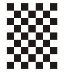
Fisheye Lens Calibration Plate
The extrinsic parameter calibration module is used to determine the attitude and position of the four fisheye lenses relative to the flat ground calibration plate, for later use in the panoramic fusion algorithm. This module is also used as a new value for the next intrinsic parameter iteration when calculating the extrinsic parameters using the least squares method, thus linking it with the intrinsic parameter calibration module. The calculations in this module primarily utilize SVD matrix solving and combine the unit orthogonal properties of the coordinate transformation matrix to ultimately obtain the extrinsic parameter matrices for the four cameras.
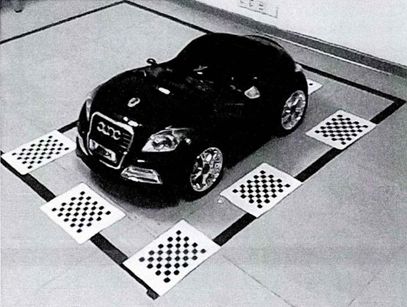
Extrinsic Parameter Calibration Diagram
The surround view stitching module uses the intrinsic and extrinsic parameter values obtained from the previous two modules, applying coordinate transformations to normalize them to a unified coordinate system, and ultimately synthesizing the panoramic surround view effect. This module mainly consists of four parts: First, transform the coordinate systems of the four checkerboards into a unified vehicle coordinate system through coordinate transformation. Then, within the unified coordinate system, divide the area around the vehicle into four subsystems, and index the pixel values in the original image coordinate system based on the obtained intrinsic and extrinsic data for reprojection. Next, perform surface reprojection for the outer stereoscopic parts. Finally, based on the principle of area fusion for the flat and curved parts, merge the synthesized images to eliminate stitching gaps and obtain the final surround view image.

How to Find Me
1. Click the blue text at the top Shenzhen Automotive Electronics Industry Association to follow;
2. Search for the WeChat public account: “Shenzhen Automotive Electronics Industry Association” or “qidianxiehui”;
3. Scan the QR code to follow