


RC Parallel Design Between PCB GND and Chassis GND:
Principles, Advantages, and Application Comparisons
-Compare-
Enning EMC Engineering



Summary
Overview Prospect feed
In metal-cased electronic devices, the connection design between PCB GND (signal ground / PCB ground) and chassis GND (enclosure ground / protective ground) directly affects the electrical safety, electromagnetic compatibility (EMC), and signal integrity of the device. A direct short can easily introduce ground loop noise, while complete floating cannot discharge high-frequency interference. The “resistor (typically 1MΩ~10MΩ) + capacitor (typically 1nF~100nF) in parallel” (referred to as RC grounding) is a classic solution that balances the needs of all three aspects, and its core logic and specific advantages can be detailed as follows.
Core Principle of RC Parallel Design
The essence of RC parallel is to utilize the characteristic differences of capacitors “low impedance at high frequency, high impedance at low frequency” and resistors “high impedance at high frequency, low impedance at low frequency” to play different roles in different frequency scenarios, achieving “full coverage protection for both high and low frequency scenarios”.
01
Capacitor: “Low Impedance Discharge Path” for High-Frequency Noise
Capacitors have extremely low impedance to high-frequency signals (the formula is
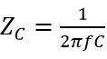
As frequency f increases and capacitance C increases, impedance decreases), thus mainly responsible for the discharge and suppression of high-frequency interference, with specific functions divided into two categories:
-
High-Frequency Noise Bypass (Anti-External Interference)
Metal enclosures can easily couple external high-frequency interference (such as RF signals, switching power supply radiation noise, external electromagnetic radiation, etc.) through electromagnetic induction. If this interference directly enters the PCB, it can lead to chip mis-triggering and signal distortion. The parallel capacitor can serve as a “high-frequency pathway,” directing high-frequency interference from the enclosure to the chassis ground (ultimately connecting to the earth) via a low-impedance path, preventing interference from invading the internal circuit (similar to an auxiliary enhancement of a “Faraday cage,” further blocking high-frequency interference transmission).
Capacitance selection basis: 1nF~100nF is the range that balances “high-frequency response” and “safety” — this capacitance can have an impedance as low as a few ohms to dozens of ohms in the 1MHz~100MHz frequency band (common high-frequency interference band for electronic devices), effectively discharging interference; if the capacitance is too large (e.g., 1μF), it may generate additional leakage current in the low-frequency band, violating safety design.
-
Suppress EMI Radiation (Prevent Internal Interference Leakage)
If the high-frequency signals from the PCB (such as CPU clock signals, power transistor switching signals) leak to the enclosure through radiation or conduction, it can cause the device to fail EMC testing (such as radiation disturbance testing RE). The capacitor can “preemptively intercept” high-frequency noise on the PCB GND, directing it to the earth through the chassis GND, reducing the intensity of noise leakage and helping the device meet EMC certification requirements (such as CE, FCC certification).
02
Resistor: “Safety Isolation Barrier” for Low-Frequency Scenarios
Resistors have a constant impedance (ZR=R), and selecting a high resistance parameter of 1MΩ~10MΩ mainly provides isolation and safety protection in low-frequency scenarios, with specific functions including:
-
Block Ground Loop Current (Anti-Low-Frequency Interference)
If the PCB GND is directly shorted to the chassis GND, the grounding points (e.g., PCB ground connected to the power supply negative, chassis ground connected to the building ground) may produce a “potential difference” due to wiring length and grounding resistance differences. In low-frequency scenarios (such as 50Hz/60Hz industrial frequency electricity, audio signal frequency band), this potential difference can form “ground loop current,” ultimately converting into audible noise (such as the “hum” in audio equipment) or analog signal distortion. A high-resistance resistor of 1MΩ~10MΩ can significantly weaken ground loop current (according to Ohm’s law, current is inversely proportional to resistance), preventing low-frequency interference from the source.
-
Safety Protection (Current Limiting to Prevent Electric Shock)
For devices connected to AC mains (such as 220V/110V), if the internal circuit insulation fails, mains electricity may conduct to the enclosure through the PCB GND. At this time, the resistor can limit the size of the “leakage current”: for example, with 220V mains, a 1MΩ resistor corresponds to a leakage current of about 0.22mA, close to the international safety standard (such as IEC 60950) requirement for “leakage current of accessible metal parts < 0.1mA” (in actual design, the resistor value will be fine-tuned to further meet the standard), preventing the risk of electric shock when users touch the enclosure.
-
Static / High Voltage Protection (Protecting Chips)
Devices may encounter static electricity (such as human static voltage reaching thousands of volts) or instantaneous high voltage during transport or use. If directly conducted to the PCB, it may damage the chips. High-resistance resistors can significantly reduce the discharge current of static electricity / high voltage (even if the voltage is high, the current = voltage / resistance remains at the microamp level), preventing chip damage due to overcurrent.
03
Synergistic Effect of RC Parallel: Balancing High and Low Frequency Needs
The core value of RC parallel lies in “leveraging strengths and avoiding weaknesses,” allowing the two components to dominate in different frequency scenarios, achieving the dual goals of “safety + anti-interference”:
-
Low-Frequency Scenarios (such as industrial frequency 50Hz, audio signals): The capacitor has extremely high impedance (e.g., a 1nF capacitor has an impedance of about 3.2MΩ at 50Hz), and the circuit is dominated by the resistor — the high-resistance characteristic blocks ground loop current, avoiding low-frequency noise while limiting leakage current to ensure safety.
-
High-Frequency Scenarios (such as RF 10MHz, switching power supply noise): The capacitor has extremely low impedance (e.g., a 1nF capacitor has an impedance of about 1.6Ω at 10MHz), and the circuit is dominated by the capacitor — the low-resistance characteristic quickly discharges high-frequency interference, preventing interference from invading or leaking, ensuring EMC performance.
Design considerations: To maximize the RC effect, three principles should be followed: ① The RC network should be as close to the PCB grounding point as possible to reduce parasitic parameters; ② The capacitor leads should be “short and thick” to avoid introducing parasitic inductance (inductance will counteract the capacitor’s high-frequency low-resistance characteristics); ③ The chassis grounding point should ensure low impedance (e.g., using conductive foam, metal springs for connection) to ensure effective interference grounding to the earth.
Comparison of RC Parallel with Other Grounding Solutions
To better understand the advantages of RC parallel, it can be compared with three common solutions: “Direct Connection,” “Only Capacitor,” and “Only Resistor,” with specific differences shown in the table below:
|
Connection Method |
Core Advantages |
Core Disadvantages |
Applicable Scenarios |
|
PCB GND Directly Connected to Chassis |
Simple circuit, extremely low impedance |
High risk of ground loop (serious low-frequency noise); excessive leakage current, high safety hazard |
Special scenarios without low-frequency interference or mains connection (rarely used) |
|
PCB GND Only Connected Capacitor to Chassis |
Excellent high-frequency EMI suppression |
No low-frequency isolation (may introduce ground loop); no leakage current limitation, high safety risk |
High-frequency sensitive devices (such as RF modules), and no mains connection |
|
PCB GND Only Connected Resistor to Chassis |
Good ground loop prevention, high safety |
High-frequency noise cannot be discharged, poor EMC performance |
Low-frequency analog circuits (such as audio preamplifiers), and low EMC requirements |
|
PCB GND Connected via RC Parallel to Chassis |
Balances safety (current limiting) and anti-interference (full coverage for high and low frequency) |
Need to weigh RC parameters based on scenarios (such as balancing high-frequency needs and safety needs) |
Most general devices (such as industrial controllers, consumer electronics, medical devices, etc.) |

Conclusion
The RC parallel design between PCB GND and chassis GND is a classic case in electronic engineering of “solving multiple demand conflicts based on component characteristics” — using capacitors to address high-frequency EMC issues and resistors to solve low-frequency safety and interference problems, ultimately achieving the threefold goal of “electrical safety compliance, EMC performance standards, and signal integrity assurance.” For this reason, this solution is widely used in various metal-cased devices, becoming the preferred grounding solution that balances practicality and reliability.
– END –
Statement
This account maintains neutrality regarding reprints, sharing, statements, and opinions, with the purpose of conveying more information. Copyright belongs to the original author. If there are copyright issues, please contact this public account, and we will delete it as soon as possible! For works declared as original, reprints require application and authorization from this account!




WeChat Official Account丨Enning EMC Engineering
Official Website丨enshco.com