Introduction
This article will continue to delve into the issue of current backflow, analyzing the root causes of IO port damage and system stability problems in embedded systems.
In the previous engineering notes, we learned about current backflow and discussed a series of problems it may cause, including IO port damage, system crashes, failure to boot, or abnormal sleep and wake-up issues. Although these problems sound quite technical, they are crucial for the normal operation of embedded systems. In this issue, we will analyze the reasons behind these phenomena in depth.
 IO Port Damage
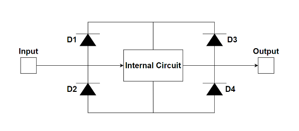
-
D1 serves as an anti-static feature in most integrated circuits, while also limiting input levels.
-
D2 is a parasitic diode generated by semiconductor integration, providing some discharge protection.
-
D3 protects CMOS circuits from interference during discharge, and this diode also exists in most bipolar devices.
-
D4 is a parasitic diode of the collector (bipolar) or drain (FET) of the transistor, providing discharge functionality.
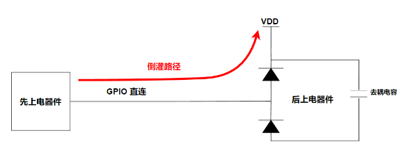
Next, we will analyze the process of how current backflow damages the IO port, in conjunction with Figure 2. In a scenario where there is a power-up sequence (or when the right-side device is powered off or disconnected), if the voltage on the left side is sufficiently high, it will charge the right-side VDD through the diode, which means charging the decoupling capacitor. This can cause the diode to rapidly overload and fail, and the capacitor itself may also be damaged. A sudden large current can even directly destroy the components themselves; no matter how good the structure is, it can cause the device logic to malfunction.
 System Failures
1. System Crashes and Failure to Boot
Generally speaking, the PMU used in conjunction with the SOC has an internal DC-DC leakage detection feature. When the PMU is not powered on, if leakage is detected on a certain DC-DC and the leakage voltage exceeds the VIL (TYP) value, that DC-DC will not output voltage. Therefore, the system will fail to boot due to the lack of voltage output from a certain DC-DC of the accompanying PMU. At this point, the measured voltage on the DC-DC power network is actually the leakage voltage.
If a certain DC-DC of the PMU powers both the SOC and some peripherals, and many of the SOC’s GPIOs use the power domain of that DC-DC, the power supply of the peripherals may also leak to that DC-DC through GPIOs. If the SOC chip enters sleep mode, the backflow phenomenon can cause abnormal wake-up from sleep.
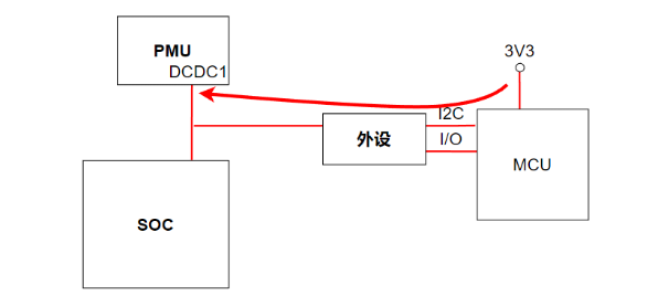
As shown in Figure 3, when the SOC chip enters sleep mode, the MCU’s I2C/UART/IO powers up before DCDC1, causing the level to backflow to DCDC1 through the peripherals, resulting in abnormal sleep behavior.