Produced by 21ic Forum gaoyang9992006Website: bbs.21ic.com
Prerequisite: Install Keil for ARM, install the Nuvoton pack, and download the Nuvoton BSP standard library files.
Create a folder to store the upcoming project files.
This demonstration uses the Nuvoton M263A series development board.
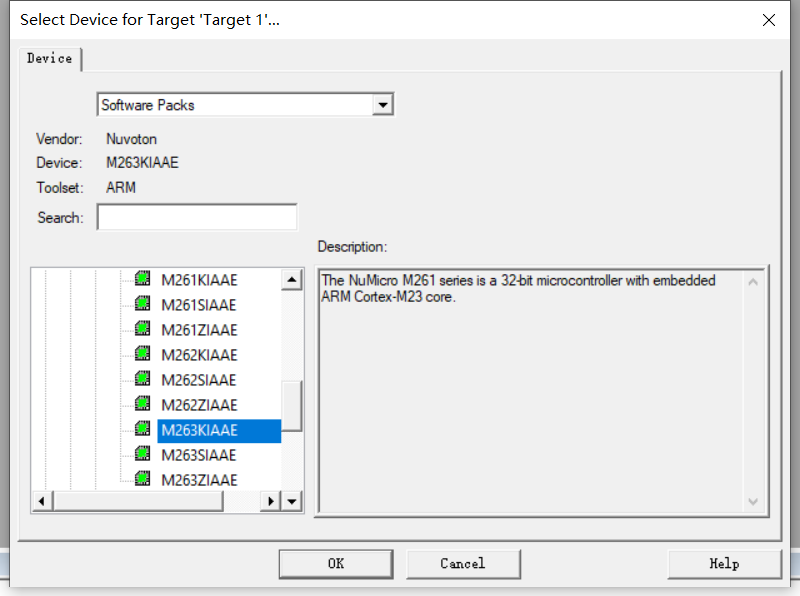
Create a Keil project, locate the Nuvoton directory, and select the specific microcontroller you are using from the M23 series; this time, we choose M263KIAAE.
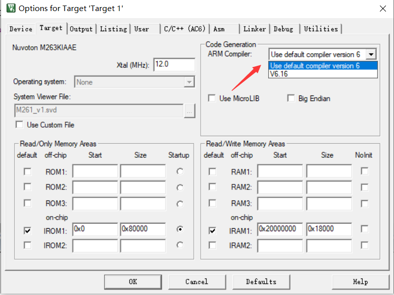
As you can see, only AC6 can be selected, indicating that this series is very new, and the manufacturer has provided relevant support files according to the latest AC6 standards.
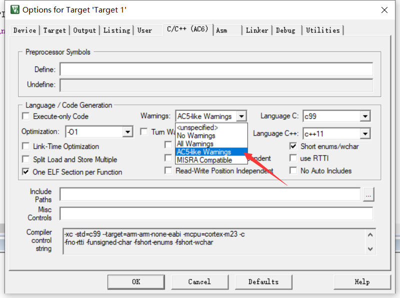
To prevent excessive warnings, select AC5-Like in the warning options.
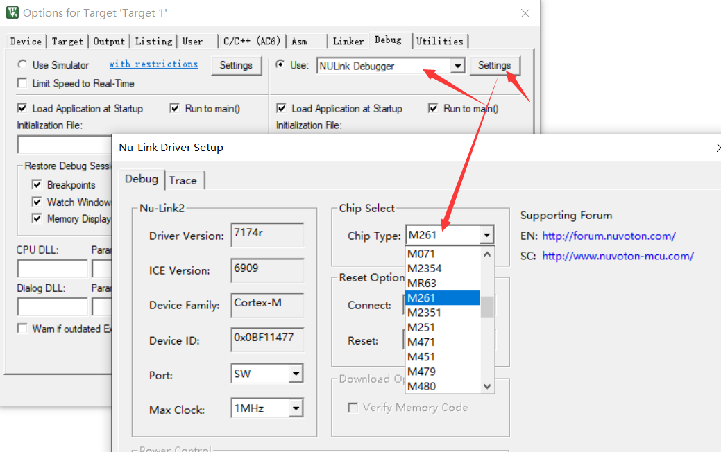
Select the Nuvoton debugger and set the chip model to the one you are currently using.
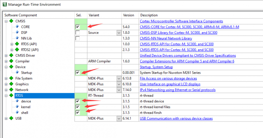
Next, in the RTE configuration, select the following basic items.
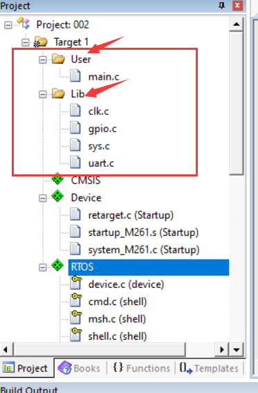
Add User and Lib directories to the newly created project to store your own code and the peripheral standard libraries you will use, generally following at least the four basic contents shown in the image below.
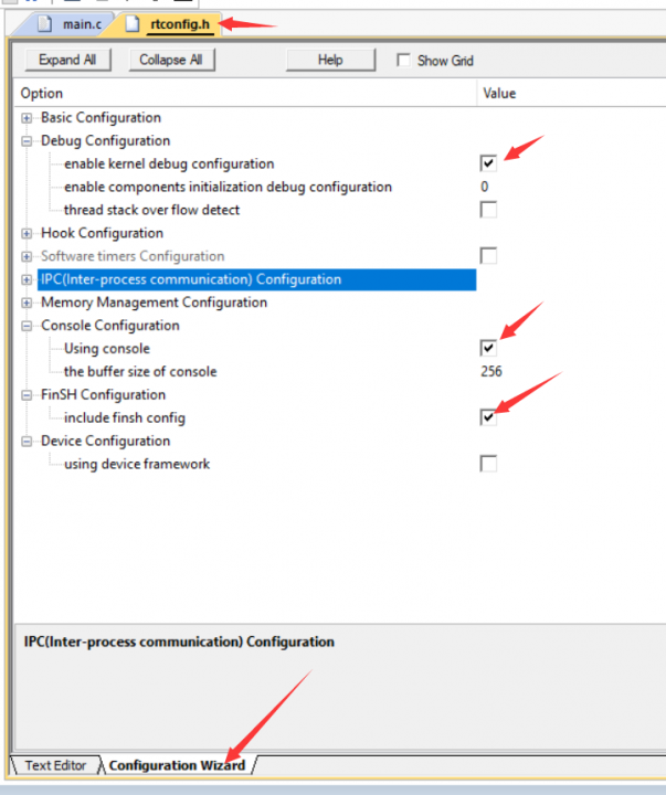
Next, configure the RTOS configuration file.
Include the Nuvoton header file in board.c and finsh_port.c.
#include <NuMicro.h>
Then in board.c, according to the precompiled error prompts, complete each item, a total of four items.
1. Find the M263 BSP, copy the system initialization function from the template project, and add a function to enable the SysTick clock.
void SYS_Init(void)
{
    /* Unlock protected registers */
    SYS_UnlockReg();

    /* Enable HIRC clock (Internal RC 48MHz) */
    CLK_EnableXtalRC(CLK_PWRCTL_HIRCEN_Msk);

    /* Wait for HIRC clock ready */
    CLK_WaitClockReady(CLK_STATUS_HIRCSTB_Msk);

    /* Select HCLK clock source as HIRC and HCLK source divider as 1 */
    CLK_SetHCLK(CLK_CLKSEL0_HCLKSEL_HIRC, CLK_CLKDIV0_HCLK(1));
                CLK_EnableSysTick(CLK_CLKSEL0_STCLKSEL_HCLK , SystemCoreClock / RT_TICK_PER_SECOND);

    /* Enable UART0 clock */
    CLK_EnableModuleClock(UART0_MODULE);

    /* Switch UART0 clock source to HIRC */
    CLK_SetModuleClock(UART0_MODULE, CLK_CLKSEL1_UART0SEL_HIRC, CLK_CLKDIV0_UART0(1));

    /* Update System Core Clock */
    SystemCoreClockUpdate();

    /* Set PB multi-function pins for UART0 RXD=PB.12 and TXD=PB.13 */
    SYS->GPB_MFPH = (SYS->GPB_MFPH & ~(SYS_GPB_MFPH_PB12MFP_Msk | SYS_GPB_MFPH_PB13MFP_Msk))    |       \
                    (SYS_GPB_MFPH_PB12MFP_UART0_RXD | SYS_GPB_MFPH_PB13MFP_UART0_TXD);

    /* Lock protected registers */
    SYS_LockReg();
}
The following line is our addition.
CLK_EnableSysTick(CLK_CLKSEL0_STCLKSEL_HCLK , SystemCoreClock / RT_TICK_PER_SECOND);Then reference it in the rt_hw_board_init() function in that file and comment out the first line of the function #error TODO 1……
And improve the SysTick interrupt entry function after the rt_os_tick_callback() function.
void SysTick_Handler(void)
{
        rt_os_tick_callback();
}
Find the second #error TODO2……
This function is uart_init, used for serial port initialization; here, we simply open the serial port tool, and our development board connects to the computer via serial port 0, so it should look like this:
static int uart_init(void)
{
//#error "TODO 2: Enable the hardware uart and config baudrate."
        UART_Open(UART0,115200);
    return 0;
}
Find the last third #error TODO3……
Modify it as follows, directly calling the serial output function from the BSP standard library, one line is sufficient.
void rt_hw_console_output(const char *str){
//#error "TODO 3: Output the string 'str' through the uart."
        UART_Write(UART0,(uint8_t *)str,rt_strlen(str));
}
Fourth, find the #error TODO4…… in finsh_port.c.
Copy the statement used for output in the redirection directly.
RT_WEAK char rt_hw_console_getchar(void)
{
    /* Note: the initial value of ch must < 0 */
    int ch = -1;

//#error "TODO 4: Read a char from the uart and assign it to 'ch'."
        if((DEBUG_PORT->FIFOSTS & UART_FIFOSTS_RXEMPTY_Msk) == 0U)
        {
            return ((char)DEBUG_PORT->DAT);
        }
    return ch;
}
DEBUG_PORT can be replaced with UART0, or it can remain unchanged, because this macro is defined in the system_M261.h header file as a substitute for UART0.
Finally, complete the main function in the simple main.c file, using the RTT provided print and delay functions to test whether the porting is successful.
#include<rtthread.h>
#include<NuMicro.h>
int main(void){
        GPIO_SetMode(PB,BIT10,GPIO_MODE_OUTPUT);

        rt_kprintf("Hello,M263!\n");

        while(1)
        {
                rt_thread_mdelay(500);
                PB10 ^=1;
        }
}
Finally, save and compile.
Open the serial port assistant, then click download, and observe the messages printed by the serial port assistant.
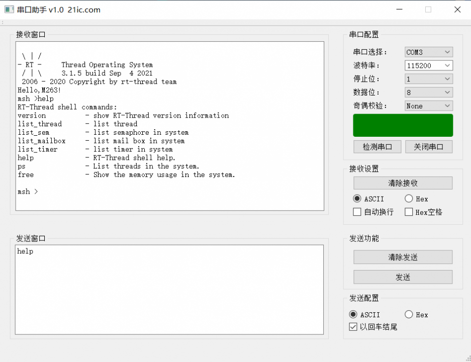
Done! At the same time, the LED on the development board starts to blink, indicating that both the delay function and the serial printing have been successfully ported, and the system has controlled the SysTick timer to work normally.
Note: Here we do not need to redirect the file to mask hardware error interrupts because the redirection file uses new function names that do not overlap with those used by the RTOS, so it does not conflict.
Thus, it is simpler than porting the M0 and M4 series.
This article is original by 21ic Forum user gaoyang9992006, for data download please click “Read Original” to download▍Recommended Reading:Officially Recognized! Programmers Become “New Generation Migrant Workers”Regrettable! 31-Year-Old Entrepreneur Dies in NIO “Automatic Assisted Driving”Revealed! The Chinese Olympic Delegation of 777 People Has Zero COVID Infection, It Turns Out There Is a “Divine Tool” Behind It 21ic Exclusive “Cultivation Manual” | Must-Read Electronics Public Account | Electronics “Design Toolkit”
Add Administrator WeChat
What exactly is the difference between you and the top engineers?Join the technical exchange group and face-to-face with experts