Click the blue text above to follow us
How the MCU Decodes Resolver Signals
How does the MCU decode resolver signals
Core Overview
Parsing resolver signals is a collaborative process involving a “dedicated hardware chip (RDC) + general-purpose software algorithm (MCU).” The core division of labor is as follows:
⚡RDC: Responsible for the lowest level, computationally intensive, and high real-time tasks.Accurately converting the analog sine/cosine signals output by the resolver into digital angle values. This is a purely hardware process.
⚡MCU: Responsible for higher-level application tasks. Reads the digital angle values provided by the RDC and uses software algorithms to calculate speed and direction, ultimately enabling advanced motor control algorithms.
Core Overview of Signal Parsing: Division of Labor and Collaboration
Parsing resolver signals is a collaborative process involving a “dedicated hardware chip (RDC) + general-purpose software algorithm (MCU).” The core division of labor is as follows:
⚡RDC (Resolver-to-Digital Converter):
Handling tasks that are low-level, computationally intensive, and require high real-time performance.
Accurately converting the analog sine/cosine signals output by the resolver into digital angle values. This is a purely hardware-driven process.
⚡MCU (Motor Control Unit): Handles higher-level application tasks: reading the digital angle values provided by the RDC and using software algorithms to calculate speed and direction, ultimately enabling advanced motor control algorithms.

Working Principle | Analog Signal | Digital Angle | Control Information
1
Working Principle of the Resolver Sensor
Working Principle of the Resolver Sensor
Pure electric vehicle drive motors typically use brushless variable reluctance (VR) type resolvers.
1. Physical Structure
⚡Rotor: An iron core with concave and convex teeth, the contour of which determines the accuracy of the output signal. It is directly connected to the motor’s main shaft.
⚡Stator: It is wound with three sets of windings
⚡An excitation winding (Excitation Windings, R1-R2): Serves as the “primary winding” and receives high-frequency excitation signals from the RDC.
⚡Two output windings: Spatially separated by exactly 90 electrical degrees.
Sine Winding (SIN, S3-S1)
Cosine Winding (COS, S2-S4)
2. Principle of Signal Generation (Electromagnetic Induction)
The MCU applies a high-frequency sinusoidal excitation signal (e.g., 10 kHz, 7 Vrms) to the excitation winding of the stator through the RDC chip.
This excitation signal generates a high-frequency alternating magnetic field around the excitation winding.
The magnetic field crosses the air gap and reaches the salient poles of the rotor. As the rotor rotates, the air gap magnetic flux undergoes regular variations due to the difference in magnetic reluctance between the teeth and slots.
This varying magnetic reluctance modulates the original magnetic field, thereby inducing voltage signals in the sine and cosine windings of the stator, whose amplitudes vary with the rotor angle.
The mathematical models of the two final output signals are:
V_sin = K * Ve * sin(θ)
V_cos = K * Ve * cos(θ)
§ Ve: Excitation signal amplitude
§ K: Transformer ratio
§ θ: Instantaneous rotor mechanical angle
Note:
Mechanical Angle = Electrical Angle / N
N is the number of pole pairs.
Example:
If the rotor has 2 poles (i.e., 1 pole pair, N=1), when the rotor completes one full rotation, the mechanical angle changes by 360°, and the electrical angle also changes by 360°.
If the rotor has 4 poles (i.e., 2 pole pairs, N=2), when the rotor completes one full rotation, the mechanical angle changes by 360°, while the electrical angle changes by 720°.
2
RDC: From Analog Signal to Digital Angle
This is the most critical and specialized step in the entire decoding process, accomplished by a dedicated chip.
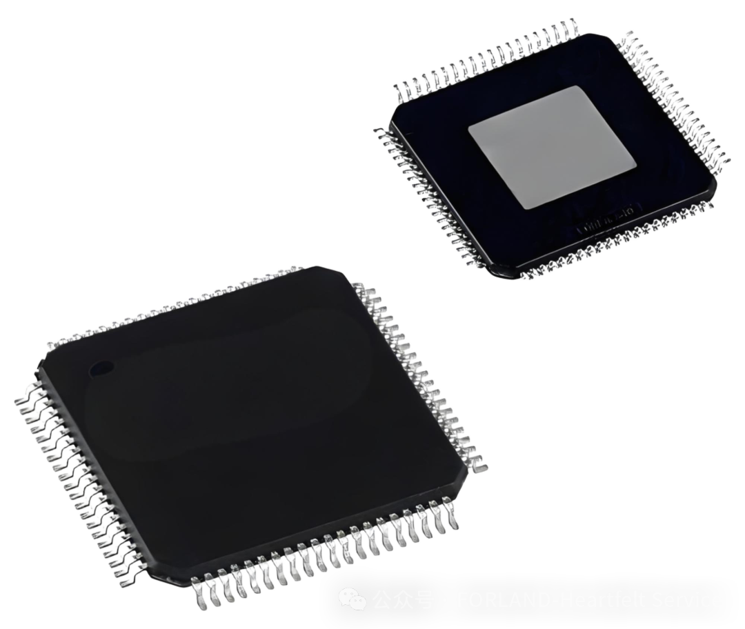
1. Signal Conditioning (Optional but Common): The SIN/COS signals from the resolver are very weak (typically only a few hundred millivolts) and may contain noise. Before being sent to the RDC, they are usually passed through a signal conditioning circuit (including amplifiers and filters) for amplification and filtering.
2. Type II Tracking Loop: The core of the RDC is a high-performance closed-loop control system, which is essentially a second-order phase-locked loop (PLL). The workflow is as follows:
⚡Angle Prediction: There is an angle register inside the loop that represents the current angle estimate θ’.
⚡Sine/Cosine Generation: The RDC calculates sin(θ’) and cos(θ’) using θ’.
⚡Error Calculation: The RDC mixes and demodulates the received actual signals V_sin and V_cos with internally generated values to compute an error signal:
Error = V_sin * cos(θ’) – V_cos * sin(θ’)
After substituting the mathematical model, it can be deduced that Error ∝ sin(θ – θ’).
When the estimated angle θ’ is very close to the true angle θ, (θ – θ’) is small, so Error ≈ (θ – θ’). The error signal is proportional to the angle difference.
⚡Closed-Loop Correction: The error signal is fed into a loop filter. The corrected signal output from the filter drives a voltage-controlled oscillator (VCO), thereby adjusting the value of the angle register θ’ and forcing the error signal to converge toward zero.
⚡Lock: When the error is zero, the system enters the “locked” state, at which point the angle estimate θ’ in the register equals the actual mechanical angle θ.
⚡Digital Output: Once the angle is locked, the digital value in the register is output to the MCU in real time. At this point, the challenging task of “analog-to-digital” conversion is completed.
3
MCU: From the Digital Domain to Control Commands
The MCU continuously reads a series of absolute angle values θ[0], θ[1], θ[2] … θ[n] (with a sampling time interval of Δt) from the RDC and performs the following calculations through software:
1. Calculate the Signed Angular Difference (Δθ) and Determine the Direction
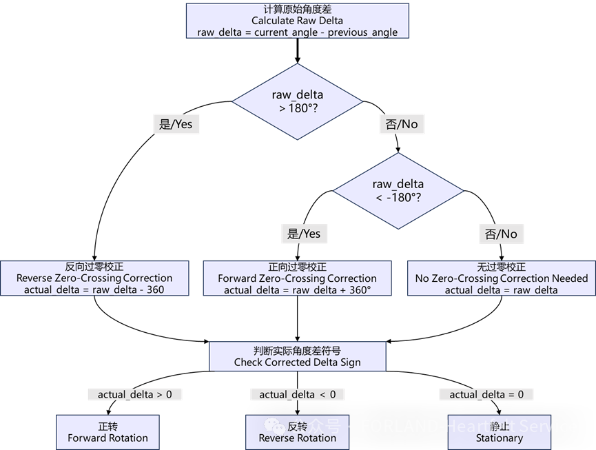
Direction Determination:
The sign of actual_delta directly indicates the direction (a positive number represents forward rotation, and a negative number represents reverse rotation).
The raw angle difference is the difference between the current angle and the previous angle, i.e.,
raw_delta = current_angle – previous_angle
⚡When raw_delta > 180°, reverse zero-crossing correction: actual delta = raw_delta – 360°;
⚡When raw_delta < -180°, forward zero-crossing correction: actual delta = raw_delta + 360°;
⚡In the absence of the above two zero-crossing correction cases, actual delta = raw_delta;
Determine the Sign of the Actual Angle Difference:
⚡actual delta > 0, indicates forward rotation;
⚡actual delta < 0, indicates reverse rotation;
⚡actual delta = 0, indicates stationary;
2. Speed (RPM) Calculation

Units:
actual_delta is in degrees “°”;
Δt is in seconds “s”;
RPM is in “revolutions per minute”:
3. Acquiring Absolute Position
The position information is directly obtained from the digital angle value “θ” provided by the RDC. This is an absolute position value. As soon as power is applied, the MCU knows the precise angle of the motor rotor within an electrical cycle.

END