-
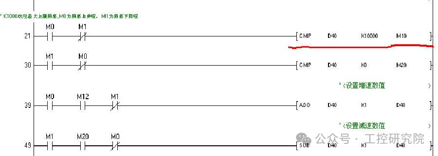
Set the upper and lower limits for the frequency set value, i.e., 0≤D40≥K10000.
-
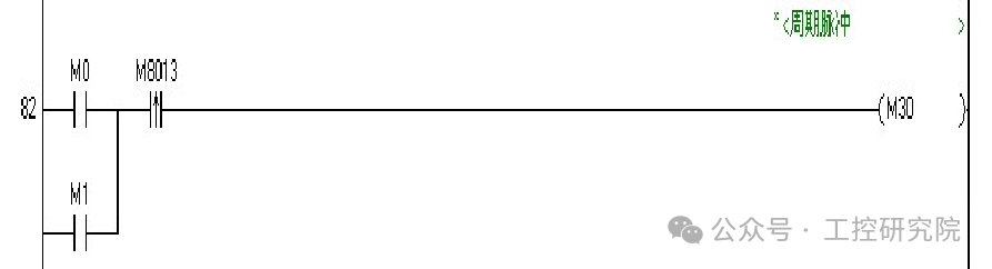
M8013 is a 1-second pulse cycle.
-
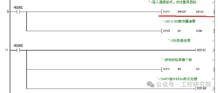
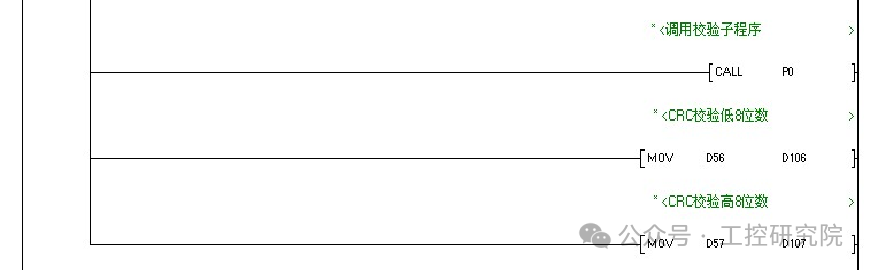
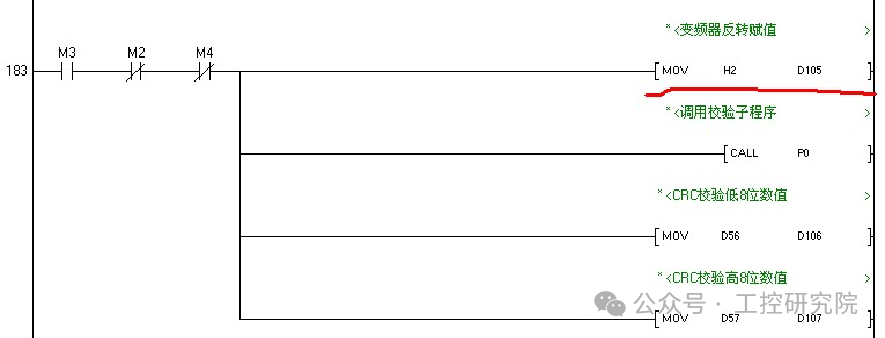
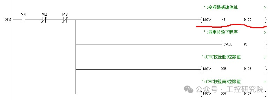
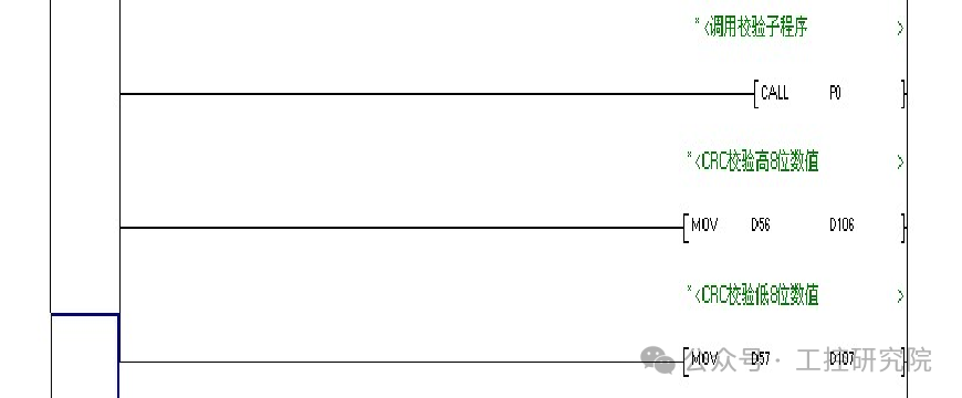
Call the P0 subroutine to execute the CRC verification program for 6 data.
-
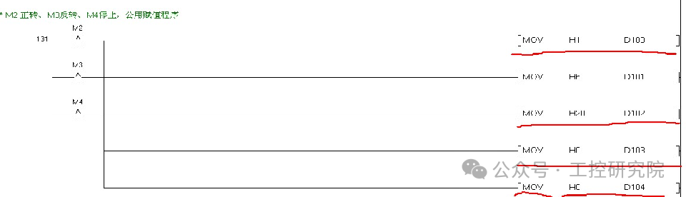
Run the control common program.
-
Use the rising edge to trigger the run control assignment program.
-
Forward run control program.

-
Reverse run control program.
-
Stop run control program.
-
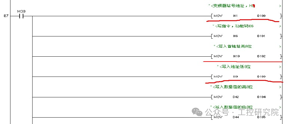
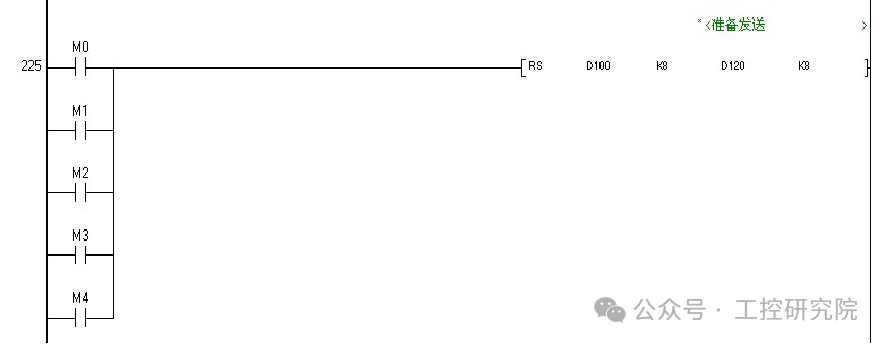
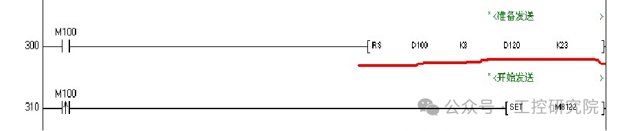
Prepare data sending program.
-
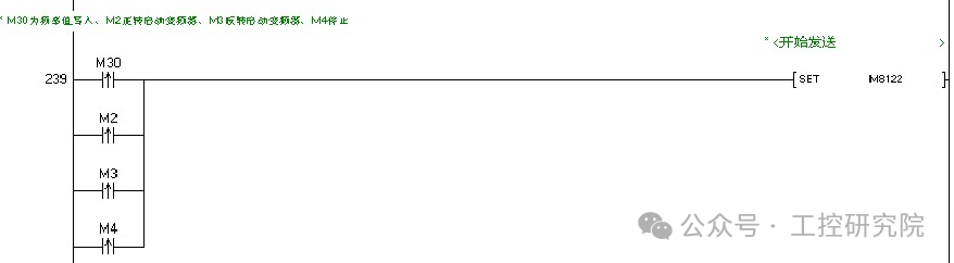
Start executing RS instruction to send data.
-
M8122 is the data sending flag relay, which can only execute the RS instruction when M8122=ON, sending and receiving data. After the data is sent, the M8122 flag will automatically reset.
-
Data sending program.
-
Note: Do not use pulse rising or falling edges to trigger the RS instruction. It is better to use pulse rising and falling edges to trigger the M8122 data sending flag relay..
-
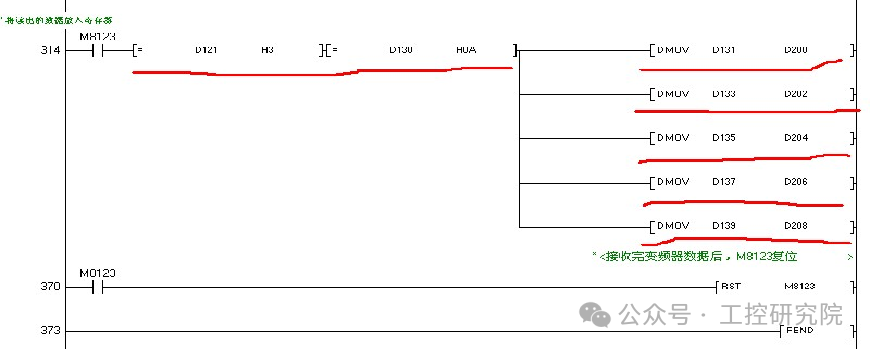
Store the 23 data returned by the inverter into PLC registers D120 to D142’s low 8 bits.
-
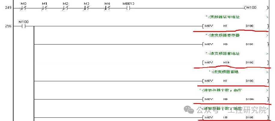
Correctly read the relevant parameter data control program.
-
DMOV D131 D200 Transfer D131 and D132 to D200 and D201 registers.
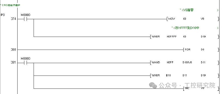
6.8. CRC Verification Subroutine Description

-
Sixteen-bit CRC verification data is stored in D10, divided into two 8-bit data.
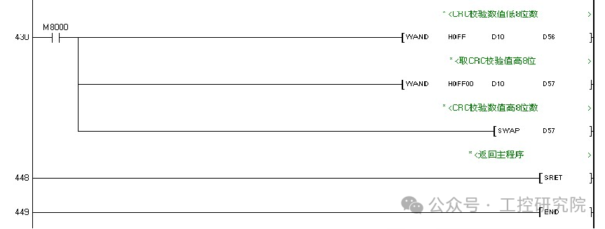
-
Byte swapping instruction SWAP D57: Swap the high 8 bits and low 8 bits in the D57 register.

Follow, forward, like, and share!