1. Configuration in TIA Portal
In TIA Portal, create a new project. This case selects the Siemens S7-300 PLC, model CPU 313C-2DP. This PLC is an integrated PLC with a built-in PROFIBUS-DP port, which can act as a master or a slave. In this case, the PLC acts as the master.
Step 1: Add the GSD file.
In TIA Portal, click on “Options” and then “Manage General Station Description Files” as shown in the figure below:
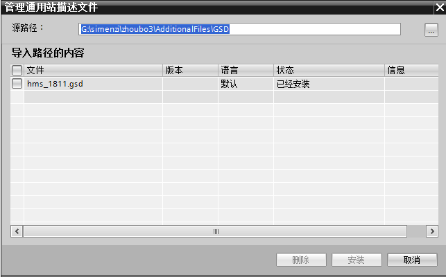
Select the GSD file and click Install. The installation may take some time depending on the computer.
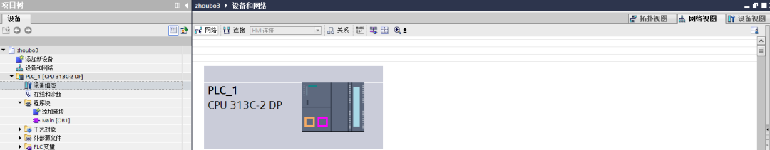
Step 2: Double-click “Device Configuration” and switch the view to Network View, as shown in the figure below:
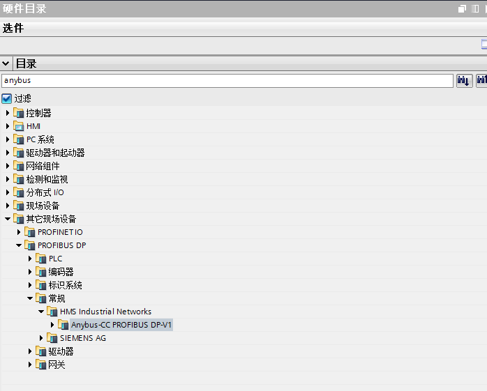
Step 3: In the right-side “Hardware Catalog” function bar, enter “anybus” in the search bar, and the following search results will appear:
Step 4: Expand Anybus-CC PROFIBUS DP-V1, hold down the left mouse button, and drag it into the Network View, as shown in the figure below:
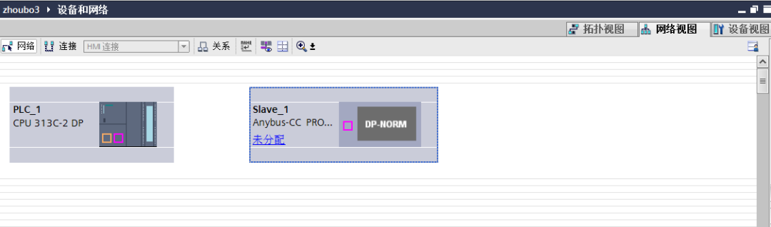
Step 5: Hold down the left mouse button to select the DP port of PLC_1 and connect it to the DP port of slave_1, as shown in the figure below:
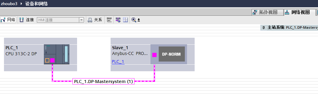
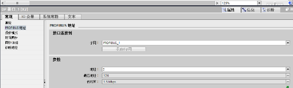
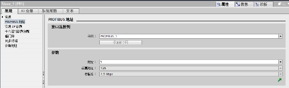
At this point, the hardware configuration between the PLC and the robot is complete. To ensure accuracy, we need to check the addresses of the master and slave. By default, the PLC as the master has an address of 2, and Slave_1, which is the robot side, has a default address of 3, as shown below:
2. Robot Side Settings
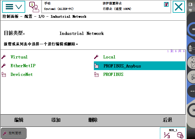
Step 1: In the “Configuration” menu of the teach pendant, ensure that the system supports Industrial Network, expand Industrial Network, and ensure that PROFIBUS_Anybus exists in the system, as shown in the figure below:
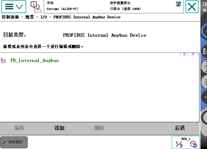
Step 2: In the “Configuration” menu, expand PROFIBUS Internal Anybus Device, as shown in the figure below:
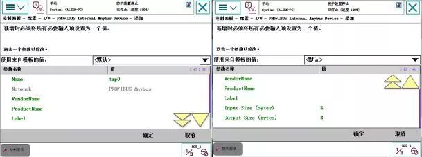
Step 3: If PB_Internal_Anybus appears in Step 2, there is no need to add it. If it does not appear, then add it, as shown in the figure below:
In the Name field, enter a name, and fill in the Input Size (bytes) and Output Size (bytes) with the corresponding communication capacity, which supports a maximum of 512 bits, or 64 bytes. The rest of the content does not need to be changed. After adding, click OK.
3. Writing the PLC Communication Program
The communication program on the PLC side is relatively simple; it only requires moving the corresponding bit values to the appropriate addresses. In this case, the PLC and the robot communicate with one byte of input and output.
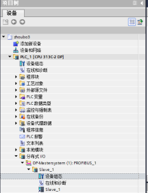
Step 1: Expand the Distributed I/O under the project tree on the left, expand it sequentially, find Device Configuration, and double-click. As shown in the figure below:
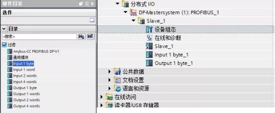
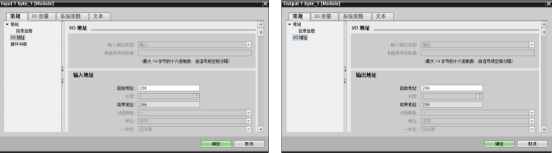
Step 2: In the right-side Hardware Catalog menu, find “Input 1 byte” and “Output 1 byte”, and double-click them respectively, so that they appear under Slave_1 on the left. This step tells the PLC that each time it sends and receives data with the robot, it is done in one byte units. As shown in the figure below:
Step 3: Determine the communication addresses of the PLC. This step is crucial as it relates to how the addresses are defined in the program. Select “Input 1 byte” and “Output 1 byte” and right-click, then select “Properties”. Here, use their default addresses as shown below:
At this point, all configurations have been completed.
Final Step: In the Main program block, add the following program:
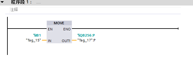
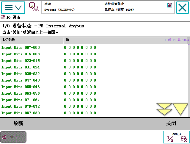
This program represents that the PLC sends the status values of channels 1.0-1.7 (one byte) to 256.0-256.7, where 256.0-256.7 corresponds to the first byte of the robot’s receiving end. We can monitor this in the IO monitoring interface of the robot’s teach pendant, as shown below:
(Source: Original by Teacher Zhinan Che)
If there are any inaccuracies, feel free to leave a comment for discussion!
You May Also Like:
Yaskawa Robot Hacking Instructions
80-page PPT, Master PLC Control Program Design
[Essentials] Non-standard Automation Equipment Development Process PPT, Very Intuitive!
[Animated] 31 Mechanical Principles Essential for Automation Design, Worth Collecting!
Mitsubishi PLC Programming Classic Cases, Definitely Useful!