The seminar is a regular activity of the Power and Mixed-Signal Integrated Circuit Laboratory, held once a month, hosted by the heads of various research directions in the laboratory. The aim is to enhance communication and integration among research groups, share cutting-edge research dynamics, and summarize stage achievements. This session will continue the content of the previous session on analog chip design, including reference circuit design presented by Sun Xuan, and temperature sensor design presented by Deng Chen.

Figure 1: Sun Xuan introduces the reference circuit content

Figure 2: Deng Chen introduces the temperature sensor chip
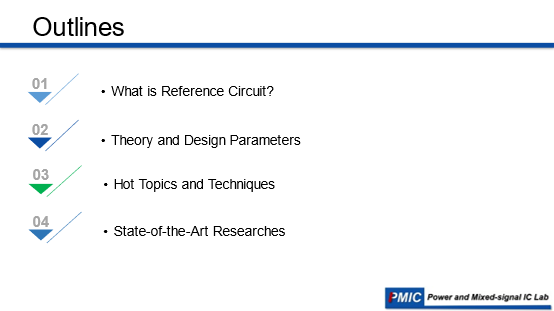
Figure 3: Reference circuit explanation directory
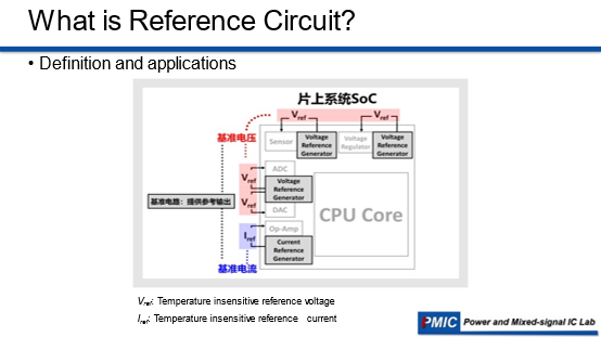
Figure 4: Application of the reference circuit

Figure 5: Design requirements for the reference circuit
The reference circuit is a critical circuit module that provides precise bias for other circuit modules. As shown in Figure 4, the reference current provides bias for operational amplifiers and other circuits; while the reference voltage provides reference voltage for ADCs, DACs, and sensors. The reference source provides an accurate and stable reference quantity for circuits or systems, and is widely used as a standard basic module in various circuits and systems.
The reference circuit needs to generate a DC current or DC voltage that is not affected by power supply voltage, temperature, and process variations. The shaded area in Figure 5 represents process deviations, and the output reference value will also change with temperature and power supply voltage. Therefore, for the reference circuit, minimizing the impact of these three factors is extremely critical. To describe it with specific metrics, if the process deviation is less than 1% without trimming, it is considered that the process impact is small and does not require additional trimming. Similarly, if the line sensitivity is less than 1% and the temperature coefficient is less than 100ppm, it is considered that the impact of power supply voltage and temperature variations is also small.
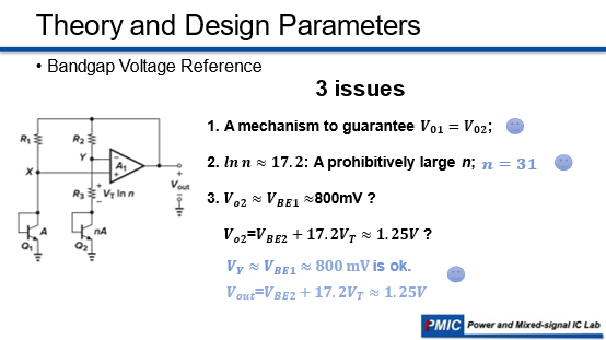
Figure 6: Temperature compensation of bandgap reference voltage
For bandgap reference circuits, the generation of PTAT and CTAT voltages is shown in Figure 6. The base-emitter voltage (VBE) of bipolar transistors, which is also the forward voltage of the pn junction diode, has a negative temperature coefficient. When two bipolar transistors operate at unequal current densities, the difference in their base-emitter voltages (△VBE) is proportional to absolute temperature, exhibiting a positive temperature coefficient. We can sum these two voltages with positive and negative temperature coefficients to obtain the reference voltage. The classic bandgap reference outputs a reference voltage value of about 1.25V, as its reference voltage value is similar to the bandgap voltage of silicon, hence it is called the bandgap reference. In fact, it does not utilize the bandgap voltage, and some bandgap structures output voltages that do not match the bandgap voltage.
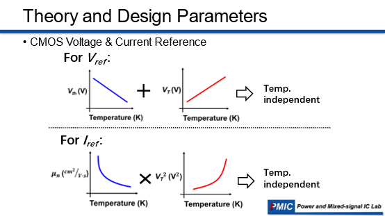
Figure 7: Temperature compensation of full CMOS reference voltage
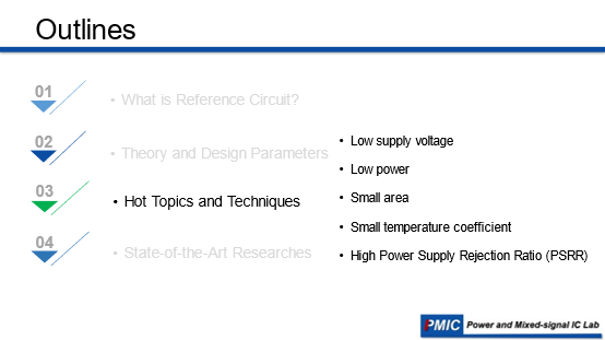
Figure 8: Research hotspots of reference circuits
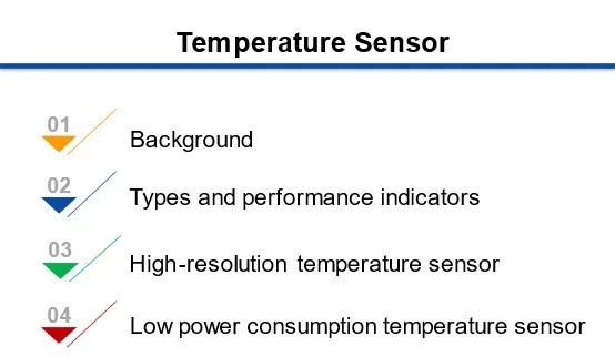
Figure 10: Temperature sensor explanation directory
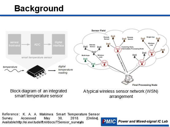
Figure 11: Application background of temperature sensor chip
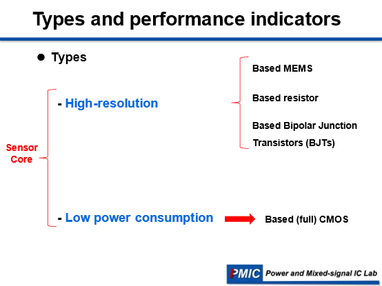
Figure 12: Classification of temperature sensors
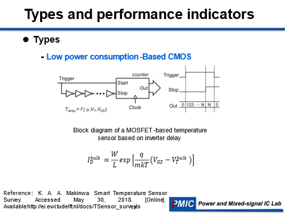
Figure 13: Example of fully CMOS integrated low-power temperature sensor
The propagation delay of a CMOS inverter chain or the frequency of a ring oscillator can also be used as a measure of temperature. Figure 13 shows the working principle of this sensor, where a counter is used to measure the propagation delay through the inverter chain.

Figure 14: Performance comparison of high-precision temperature sensors
As shown in Figure 14, among high-precision temperature sensors, circuits with MEMS as the core sensing element have the best measurement accuracy and the smallest figure of merit because MEMS are more sensitive to temperature changes compared to integrated resistors and BJTs, but they also occupy a larger area. Circuits with BJTs as sensing elements have relatively balanced performance, with relatively small measurement errors. Circuits with resistors as sensing elements have smaller areas than BJT-type temperature sensors but have larger measurement errors.
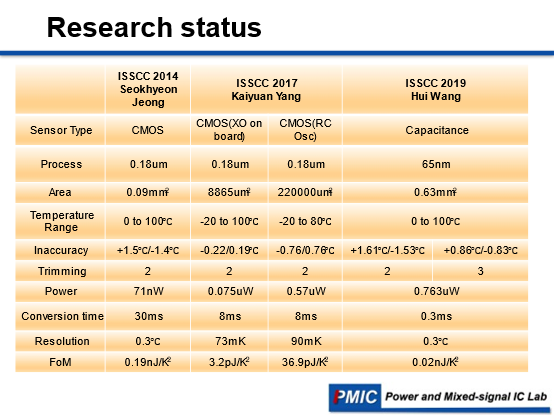
Figure 15: Performance comparison of fully CMOS integrated low-power temperature sensors
As shown in Figure 15, the development trend of fully CMOS integrated low-power temperature sensors is to continuously reduce power consumption (from nanowatt level to picowatt level), but this engineering will be accompanied by sacrifices in area or measurement error and other performances, although the sacrifices are minimal, and all performances have a good balance.


Sun Xuan and Deng Chen shared content that sparked enthusiastic discussions among everyone, and many experiences regarding the principles and methods of circuit design were shared and exchanged actively. The students in the laboratory greatly benefited from it. The PMIC seminar always brings knowledge and joy to everyone.