The ADALM-PLUTO Active Learning Module (PlutoSDR) is user-friendly and helps introduce electrical engineering students to the fundamentals of Software Defined Radio (SDR), Radio Frequency (RF), and wireless communications. This module is designed for students of varying levels and backgrounds, suitable for both teacher-led instruction and self-study, aiming to lay a foundation for practical RF and communication as students pursue degrees in science, technology, or engineering.
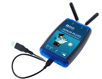
When used with a host, PlutoSDR acts as a portable laboratory, enhancing classroom learning. MATLAB and Simulink are the two main software packages supported by PlutoSDR, providing an intuitive graphical user interface (GUI) that allows students to learn faster, work more cleverly, and explore more knowledge.
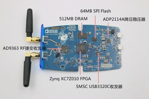
PlutoSDR features independent receive and transmit channels and can operate in full-duplex mode. The active learning module can generate or capture RF analog signals at a maximum of 61.44 MSPS within a frequency range of 325 MHz to 3800 MHz. PlutoSDR is very compact, fitting in a shirt pocket, fully self-sufficient, and powered via USB with default firmware. Since PlutoSDR starts with the libiio driver, it supports OS X®, Windows®, and Linux® allowing students to learn and explore on multiple devices.
PlutoSDR offers many available online tutorials suitable for SDR projects, with laboratory and teaching materials covering a wide range of topics such as ADS-B aircraft positioning, receiving NOAA and Meteor-M2 weather satellite images, GSM analysis, TETRA signal monitoring, and pager decoding!
MATLAB provides a simple and easy-to-use interface for accessing PLUTO, making it very convenient for users to utilize PLUTO.
We only need to consider the baseband processing part, PlutoSDR handles the “moving” of the baseband signal to the frequency band for us; we only need to set parameters such as the center frequency of the frequency band, bandwidth, gain for transmission and reception, and the number of bits that can be accommodated in a frame at the receiving end.
1. Receiving data in MATLAB.
clear allclose allclc
%pluto rx settings
rxPluto  = sdrrx('Pluto');
rxPluto.CenterFrequency = 2400000000;   % Set center frequency to 2.4GHz
rxPluto.BasebandSampleRate = 18e6;      % Set sample rate to 10MHz
rxPluto.SamplesPerFrame = 1024 ;        % Set number of samples to 1024

fs  =  rxPluto.BasebandSampleRate ;     N   =  rxPluto.SamplesPerFrame ;        freq = (-N/2:N/2-1)/N* fs/1000000 ;

% Receive signal
% data is the received signal, datavalid indicates if the data is valid, overflow indicates if the data has overflowed.
[data,datavalid,overflow] = rxPluto();  % Use Pluto for data reception
XK  =   fft( data );                    % FFT transformation
figure(1);plot(freq,20*log10( fftshift(abs( XK )) ) );  % Plot the frequency spectrum of the data
figure(2);plot(real(data)); hold on;  % Plot the real part of the data
plot(imag(data));           % Plot the imaginary part of the data
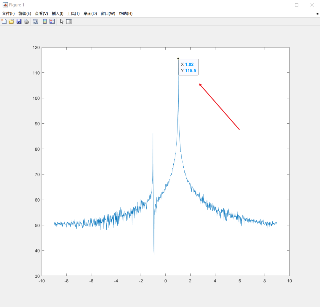
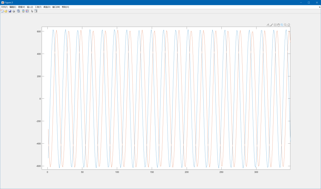
Connect Pluto via USB to the computer host and run the above MATLAB code. Input a signal with a frequency of 2.401 GHz into Pluto from the signal source, and the results are as follows.
Frequency domain graph, where a signal can be observed at 1.02 MHz.
Time domain graph, I and Q data are as follows, compared to a standard sine wave.
2. Sending data in MATLAB
Example
Send and receive a single frequency signal:
Parameter settings:
Center frequency:800MHz Bandwidth:100kHz Transmitter gain:0dB Receiver gain:30dB Default data received at the receiver:20000 bits, if you want to modify, add‘SamplesPerFrame’ in the sdrrx object,20e4, to customize the data length.
Transmitter code:
txPluto = sdrtx('Pluto','RadioID','usb:0','CenterFrequency',800e6, ...
'BasebandSampleRate',100e3,'ChannelMapping',1,'Gain',0);
modSignal=exp(1i*2*pi/128*(1:1500000)).';
i=100;
while i   txPluto(modSignal);   i=i-1 end
Run the above script, connect the Pluto TX port to an oscilloscope or spectrum analyzer, and you will observe the transmitted signal.
PlutoSDR Official Website:https://wiki.analog.com/university/tools/pluto