Introduction
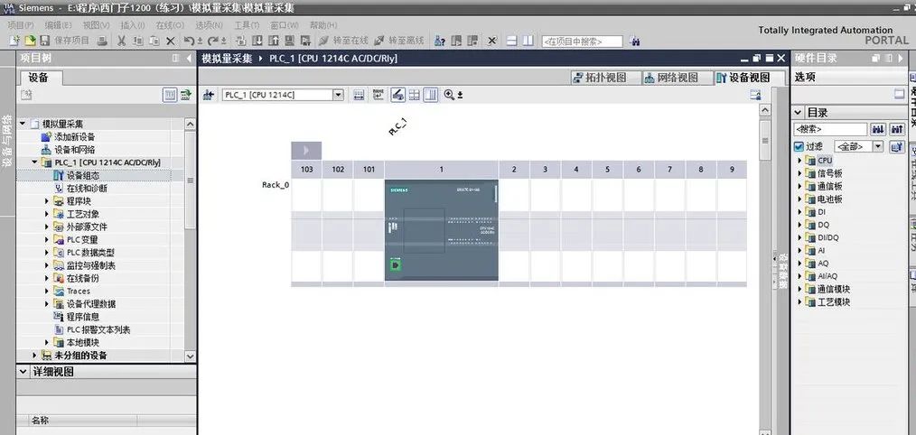
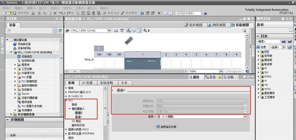
In industrial automation, analog signals are an important data type processed by PLCs, commonly found in measurements from sensors such as temperature, pressure, liquid level, and speed. Unlike digital signals that only determine ‘on’ and ‘off’, analog signals can represent continuous values. For example, the output from a temperature sensor may be a voltage signal of 0-10V or a current signal of 4-20mA. So, how does the PLC acquire these analog signals and control the output? This article will guide you step by step from basic principles to actual wiring and programming to master PLC analog input and output.
Module 1: Basic Concepts of Analog Signals
What is an Analog Signal?
An analog signal is a continuously varying voltage or current signal that represents the magnitude of a physical quantity, such as:
-
Voltage signals: Common ranges include 0-10V, -10-10V, etc.
-
Current signals: The most common are 4-20mA and 0-20mA.
Why is there a 4~20mA Standard?
4-20mA is more commonly used than 0-20mA because:
-
Stronger anti-interference capability: Current signals are less susceptible to electromagnetic interference.
-
Open circuit detection: Below 4mA can be considered as an open circuit, facilitating fault diagnosis.
How Does PLC Handle These Signals?

PLC collects and outputs signals through the analog module (AI/AO module): The analog module contains an ADC (Analog-to-Digital Converter) and a DAC (Digital-to-Analog Converter):
-
Input (AI): Converts analog signals into digital signals (for example, 0-10V corresponds to 0-2000).
-
Output (AO): Converts digital signals into analog signals (for example, 0-1000 corresponds to 0-10V).
Module 2: Analog Input – Acquiring Voltage and Current Signals
Wiring Methods
Wiring for analog input signals can be divided into two-wire and four-wire systems:
-
Two-wire: Only two signal wires between the sensor and PLC, with the current signal powered by the PLC.
-
Four-wire: The sensor has an independent power supply, and the PLC is only responsible for signal acquisition.
Wiring Diagram (4~20mA Current Input)
Below is a typical two-wire wiring diagram:
1 +24V Power Supply ------------ Sensor
2                         |
3                         |
4                     Analog Module (AI)
5                         |
6 GND --------------------
Notes:

-
Ensure the current signal circuit is closed, otherwise data cannot be collected.
-
The input end of the analog module must select the correct mode (current or voltage).
Programming Example
Assuming a Mitsubishi PLC, the input range of the analog module is 0-10V, and the PLC converts it to a digital value of 0-4000.
Ladder Diagram Program
-
First, read the register value of the analog module.
-
Then, convert the digital value to a physical quantity (such as temperature, pressure) based on the input range.
|—-[MOV D100 D0]—-| ; Write the value from the analog module register D100 into D0 |—-[DIV D0 K4000 D1]| ; Convert the digital value to a percentage (D1 = D0 / 4000) |—-[MUL D1 K100 D2]-| ; Convert the percentage to a physical quantity (assuming full scale is 100)
Code Annotation Explanation
-
D100: Input register of the analog module, used to store the collected digital signal.
-
D1: Converted percentage value.
-
D2: Final physical quantity.
Practical Case: Temperature Acquisition
A temperature sensor outputs a 0-10V voltage signal, indicating a temperature range of 0-100℃. After acquisition by the PLC, how do we display the current temperature?

-
Connect the 0-10V signal to the PLC’s AI module.
-
Use a ladder diagram program to convert the digital value to temperature.
-
Display the temperature value on the HMI (Human-Machine Interface).
Notes:
-
Ensure the output range of the sensor matches the settings of the PLC’s AI module, otherwise data may be inaccurate.
-
Add upper and lower limit alarm functions in the program, such as triggering an alarm when the temperature exceeds 100℃.
Module 3: Analog Output – Controlling Voltage and Current Signals
Principle and Wiring of Output
Analog output (AO) is used to control external devices, such as controlling the speed of a frequency converter or adjusting the opening of a valve.
Wiring Diagram (0-10V Voltage Output)
1 Analog Module (AO)
2     |
3     |---------------- Device Input
4     |
5    GND
6
Notes:
-
Ensure the input range of the load device is consistent with the PLC’s AO module.
-
If the output signal deviates significantly, check if the wiring is secure or use shielded cables to reduce interference.

Programming Example
Assuming the PLC’s AO module outputs a 0-10V voltage to control the speed of a frequency converter, with a range of 0-3000RPM.
Ladder Diagram Program
-
Calculate the required digital value (0-4000).
-
Write the digital value into the AO module’s register.
|—-[MOV D0 D200]—-| ; Write the target speed into D0 |—-[DIV D0 K3000 D1]| ; Convert the target speed to a percentage (D1 = D0 / 3000) |—-[MUL D1 K4000 D2]-| ; Convert the percentage to a digital value |—-[MOV D2 D300]—-| ; Write the digital value into the AO module register D300
Code Annotation Explanation
-
D0: Target speed.
-
D300: Output register of the AO module.
Practical Case: Frequency Converter Speed Control
Control the output frequency of a frequency converter via PLC to adjust the motor speed. The PLC outputs a 0-10V voltage signal, with a control range of 0-50Hz.
-
Connect the AO module’s output to the analog input of the frequency converter.
-
Calculate the voltage value corresponding to the target frequency in the program.
-
After testing, adjust parameters to ensure output matches expectations.

Module 4: Common Problems and Solutions
Problem 1: Analog Signal Drift
Cause: Environmental interference or poor wiring. Solution: Use shielded cables and ensure signal wires are away from strong electrical devices.
Problem 2: Signal Range Mismatch
Cause: The signal range of the sensor does not match the PLC module settings. Solution: Adjust the PLC module’s input mode or add a signal converter.
Problem 3: Unstable Output Signal
Cause: Load device impedance is too low. Solution: Check device specifications and add a buffer circuit if necessary.
Practical Suggestions
-
Select the appropriate module: Choose a matching PLC analog module based on the signal type (voltage or current) of the field sensor.
-
Calibrate the sensor: Before actual wiring, use a multimeter to measure the sensor’s output to ensure the signal is normal.
-
Test program logic: Use simulation functions or oscilloscopes to verify that input and output signals meet expectations.
-
Pay attention to safety: Cut off power before operation and avoid short circuits during wiring.
Through continuous practice, you will find that acquiring and controlling analog signals is not complicated!