Click the blue text above: IoT Inn
In the previous section, we learned about the independent key operation of the microcontroller. In fact, we used a polling method, which consumes MCU resources as it constantly checks for key presses. In this section, we will use interrupts to implement key operations.
1Introduction to STM32 IoT Kit
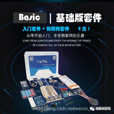
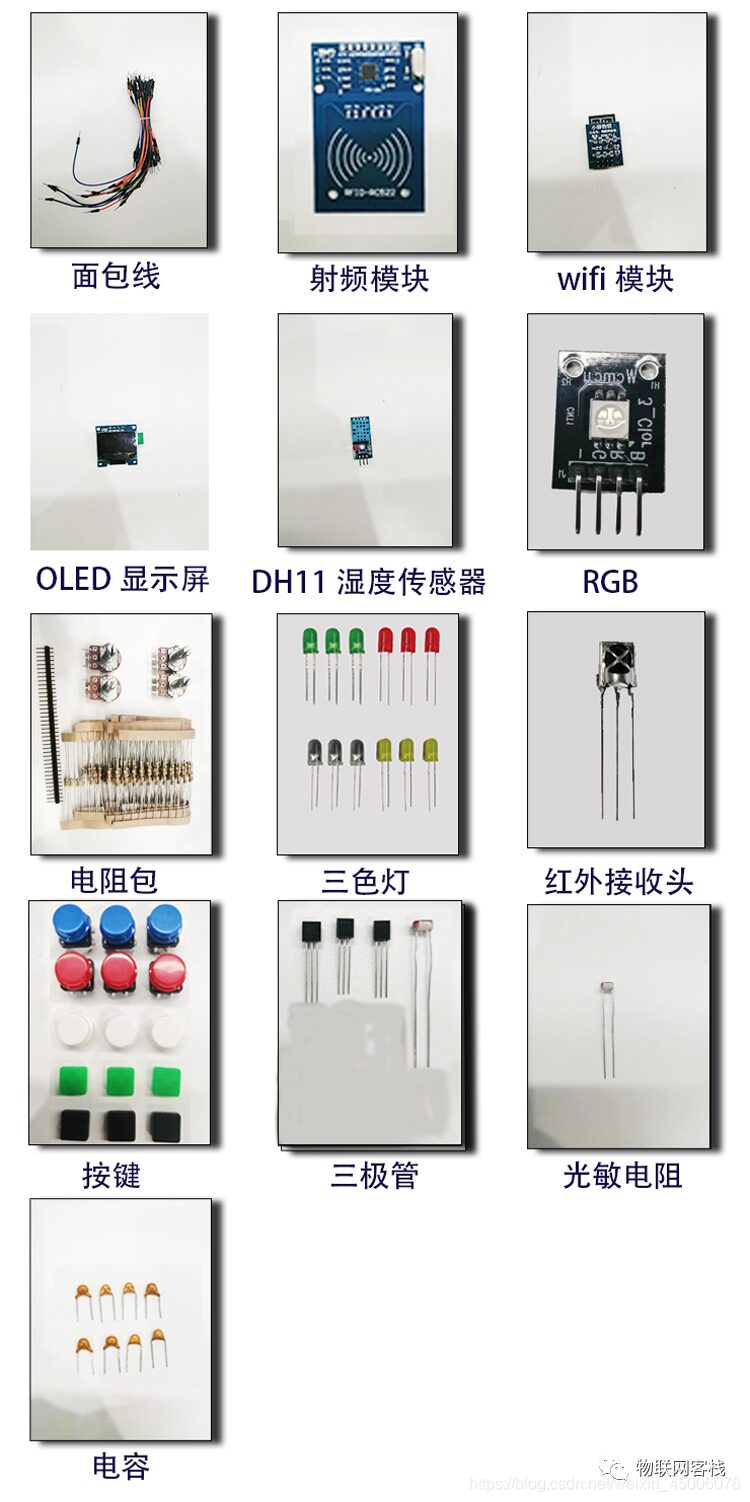
The STM32 IoT Kit currently has two versions: Basic and Advanced. Future versions will include application and voice versions. The core board uses the STM32F103C8T6 core board, and the main components of the basic version are as follows:
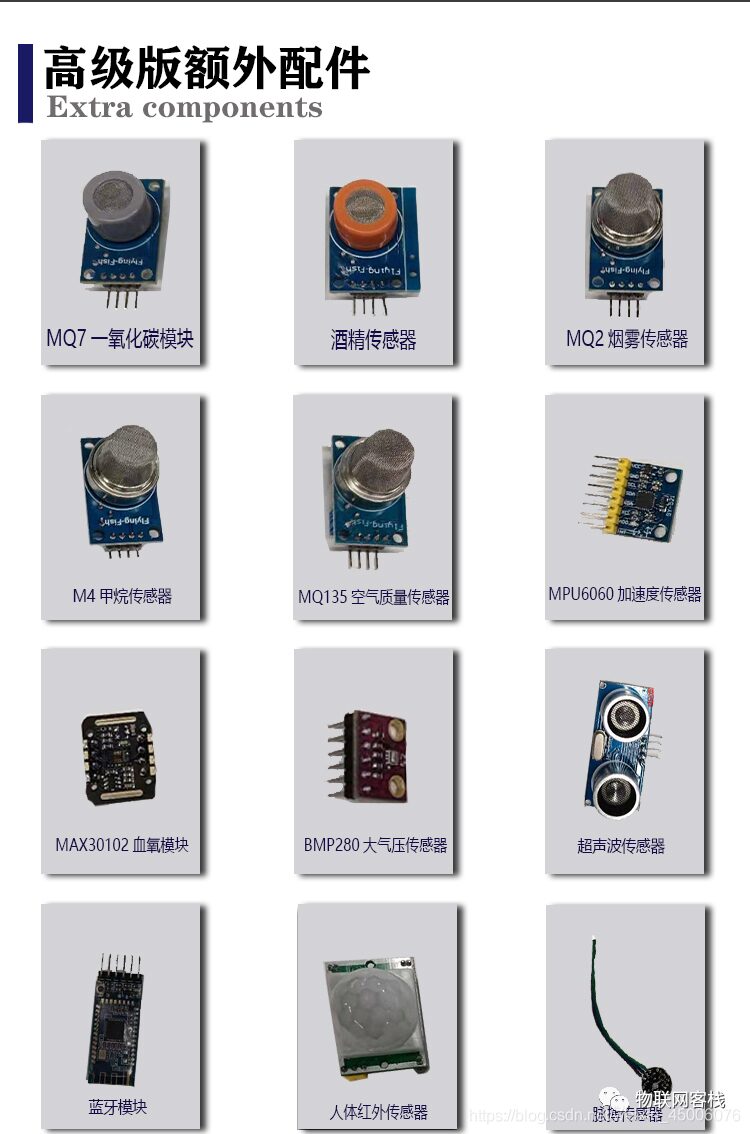
The main components of the advanced version are as follows:
The STM32 IoT Kit aims to help everyone get started with IoT. You will not only learn about STM32 but also understand the development of WeChat mini-programs and IoT server back-end development, truly grasping all aspects of an IoT project. Based on this, we have customized a universal WIFI communication protocol (which can be understood as similar to AT commands, but with higher integration, allowing direct connection to the cloud platform with just a few commands), such as three commands to connect to Tencent Cloud instances.
In the future, we will continue to add support for mainstream cloud platforms such as Tuya Smart, Telecom Cloud, Mobile Onenet, and Alibaba Cloud, striving to achieve that one set of STM32 code can connect to different cloud platforms through a customized WIFI module. We also welcome friends with product development needs to contact us for consultation and customization of IoT solutions!
This IoT kit supports university students participating in IoT-related competitions, applying for school innovation projects, and completing graduation designs. Our positioning is to be an open-source smart hardware service provider, exploring IoT together with everyone. Our mission is to promote the landing and popularization of more IoT products, making technology no longer a barrier!
2Introduction to Interrupts
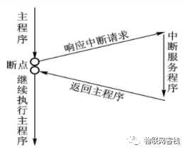
An interrupt refers to the process where the CPU, while executing event A, suddenly receives a request (interrupt) from event B, stops what it is doing, and shifts to execute event B. After event B is completed, it returns to the original point of event A where it was interrupted and continues executing the program. The diagram is as follows:
The STM32 microcontroller uses NVIC (Nested Vectored Interrupt Controller) to manage interrupts, mainly consisting of three parts: interrupt enable, preemption priority setting, and response priority setting. Note: The smaller the priority value, the higher the priority level.
Among them, interrupt enable controls whether the interrupt is open, and preemption priority is used to determine whether interrupts can interrupt each other. High preemption priority can interrupt low preemption priority (if a high preemption priority interrupt arrives while a low preemption priority task is executing, the system will pause the current task and execute the high preemption priority task, and after completion, return to execute the low preemption priority task).
When two interrupts have the same preemption priority, the system will choose which task to execute based on the corresponding priority levels.
3Interrupt Priority Grouping
The question arises, since the STM32 microcontroller can use NVIC to manage many interrupts, how many interrupts does STM32 have in total? We open the startup_stm32f103xb.s startup file to see the allocation of the interrupt vector table, as follows:
__Vectors DCD __initial_sp ; Top of StackDCD Reset_Handler ; Reset HandlerDCD NMI_Handler ; NMI HandlerDCD HardFault_Handler ; Hard Fault HandlerDCD MemManage_Handler ; MPU Fault HandlerDCD BusFault_Handler ; Bus Fault HandlerDCD UsageFault_Handler ; Usage Fault HandlerDCD 0 ; ReservedDCD 0 ; ReservedDCD 0 ; ReservedDCD 0 ; ReservedDCD SVC_Handler ; SVCall HandlerDCD DebugMon_Handler ; Debug Monitor HandlerDCD 0 ; ReservedDCD PendSV_Handler ; PendSV HandlerDCD SysTick_Handler ; SysTick Handler; External InterruptsDCD WWDG_IRQHandler ; Window WatchdogDCD PVD_IRQHandler ; PVD through EXTI Line detectDCD TAMPER_IRQHandler ; TamperDCD RTC_IRQHandler ; RTCDCD FLASH_IRQHandler ; FlashDCD RCC_IRQHandler ; RCCD EXTI0_IRQHandler ; EXTI Line 0DCD EXTI1_IRQHandler ; EXTI Line 1DCD EXTI2_IRQHandler ; EXTI Line 2DCD EXTI3_IRQHandler ; EXTI Line 3DCD EXTI4_IRQHandler ; EXTI Line 4DCD DMA1_Channel1_IRQHandler ; DMA1 Channel 1DCD DMA1_Channel2_IRQHandler ; DMA1 Channel 2DCD DMA1_Channel3_IRQHandler ; DMA1 Channel 3DCD DMA1_Channel4_IRQHandler ; DMA1 Channel 4DCD DMA1_Channel5_IRQHandler ; DMA1 Channel 5DCD DMA1_Channel6_IRQHandler ; DMA1 Channel 6DCD DMA1_Channel7_IRQHandler ; DMA1 Channel 7DCD ADC1_2_IRQHandler ; ADC1_2DCD USB_HP_CAN1_TX_IRQHandler ; USB High Priority or CAN1 TXDCD USB_LP_CAN1_RX0_IRQHandler ; USB Low Priority or CAN1 RX0DCD CAN1_RX1_IRQHandler ; CAN1 RX1DCD CAN1_SCE_IRQHandler ; CAN1 SCEDCD EXTI9_5_IRQHandler ; EXTI Line 9..5DCD TIM1_BRK_IRQHandler ; TIM1 BreakDCD TIM1_UP_IRQHandler ; TIM1 UpdateDCD TIM1_TRG_COM_IRQHandler ; TIM1 Trigger and CommutationDCD TIM1_CC_IRQHandler ; TIM1 Capture CompareDCD TIM2_IRQHandler ; TIM2DCD TIM3_IRQHandler ; TIM3DCD TIM4_IRQHandler ; TIM4DCD I2C1_EV_IRQHandler ; I2C1 EventDCD I2C1_ER_IRQHandler ; I2C1 ErrorDCD I2C2_EV_IRQHandler ; I2C2 EventDCD I2C2_ER_IRQHandler ; I2C2 ErrorDCD SPI1_IRQHandler ; SPI1DCD SPI2_IRQHandler ; SPI2DCD USART1_IRQHandler ; USART1DCD USART2_IRQHandler ; USART2DCD USART3_IRQHandler ; USART3DCD EXTI15_10_IRQHandler ; EXTI Line 15..10DCD RTC_Alarm_IRQHandler ; RTC Alarm through EXTI LineDCD USBWakeUp_IRQHandler ; USB Wakeup from suspend__Vectors_EndAmong them, from Reset_Handler to SysTick_Handler, there are a total of 10, which are non-maskable interrupts and belong to core interrupts. The remaining interrupts are external interrupts, and NVIC is responsible for managing external interrupts. Next, let’s look at interrupt priority grouping.
|
Group |
AIRCR[10:8] |
bit[7:4] Distribution |
Distribution Result |
|
0 |
111 |
0:4 |
0 preemption priority bits (0), 4 response priority bits (0-15) |
|
1 |
110 |
1:3 |
1 preemption priority bit (0-1), 3 response priority bits (0-7) |
|
2 |
101 |
2:2 |
2 preemption priority bits (0-3), 2 response priority bits (0-3) |
|
3 |
100 |
3:1 |
3 preemption priority bits (0-7), 1 response priority bit (0-1) |
|
4 |
011 |
4:0 |
4 preemption priority bits (0-15), 0 response priority bits (0) |
For example:
Set grouping 1, the preemption priority of interrupt 3 (RTC) is 1, and the response priority is 0. The preemption priority of interrupt 7 (external interrupt 1) is 1, and the response priority is 2. The preemption priority of interrupt 8 (external interrupt 2) is 0, and the response priority is 2. Thus, the priorities of the three interrupts are: interrupt 8 > interrupt 3 > interrupt 7.
4Hardware Design
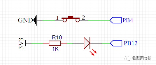
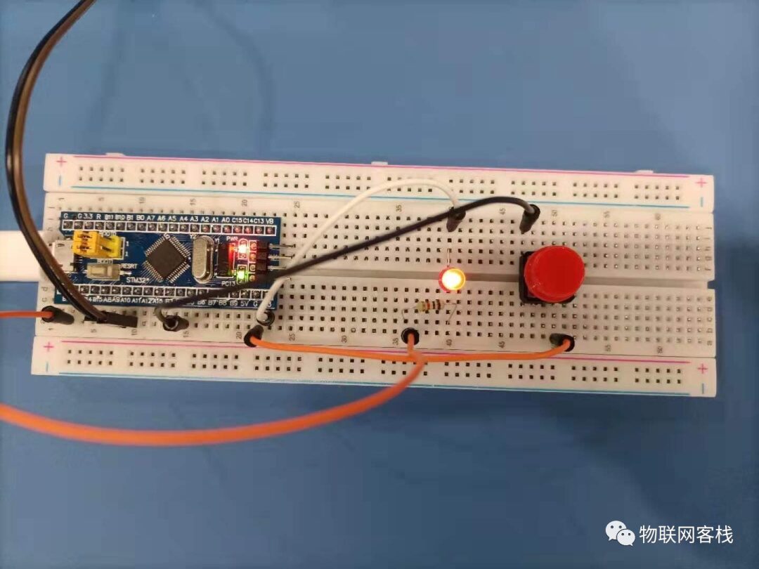
The schematic diagram of the key part of this key experiment is as follows: one end of the key is connected to ground, and the other end is connected to the microcontroller PB4. When the key is pressed, PB4 is low.
The physical diagram is as follows:
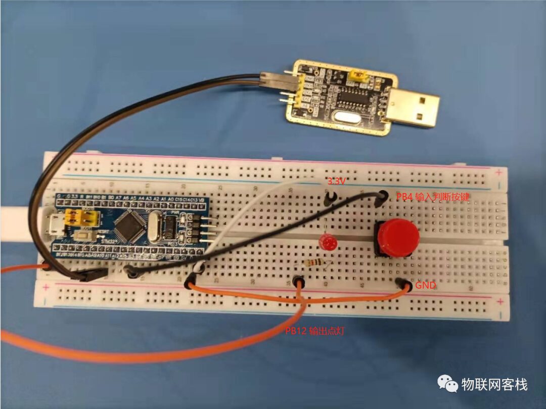
Among them, the PB12 pin outputs low voltage to light up the LED. When the key is pressed, the microcontroller detects the falling edge interrupt, and the PB4 pin is low, lighting up the LED.
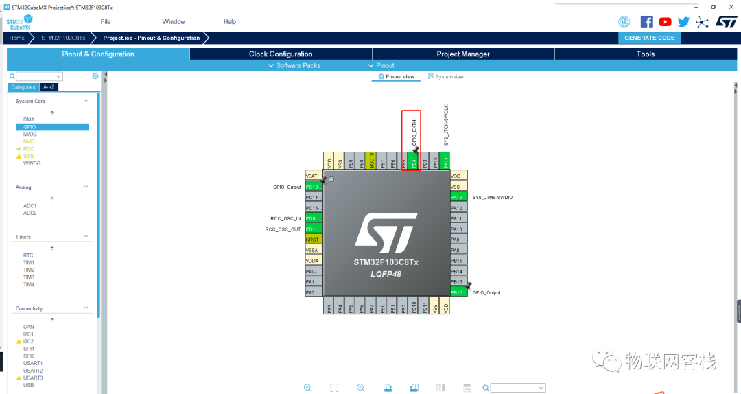
1Create a New Project
Use STM32CubeMX to create a new project, refer to the configuration method in the environment setup chapter, set RCC and PB12 pin output, and PB4 as GPIO_EXIT4.
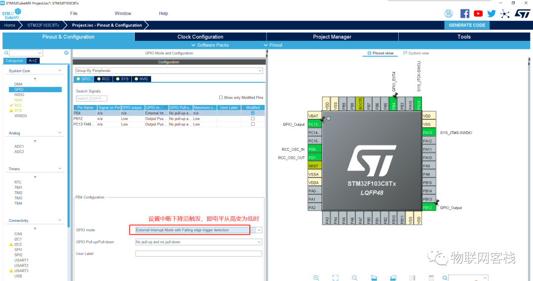
Set the interrupt trigger mode to falling edge.
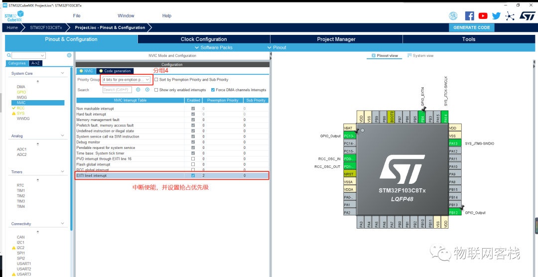
Enable NVIC to configure interrupt priority grouping 4, and enable EXIT line4 interrupt. Set GPIO preemption priority to 2.
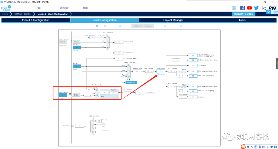
Go to the Clock configuration page, select HSE clock source, and after frequency multiplication, the main clock is 72MHz.
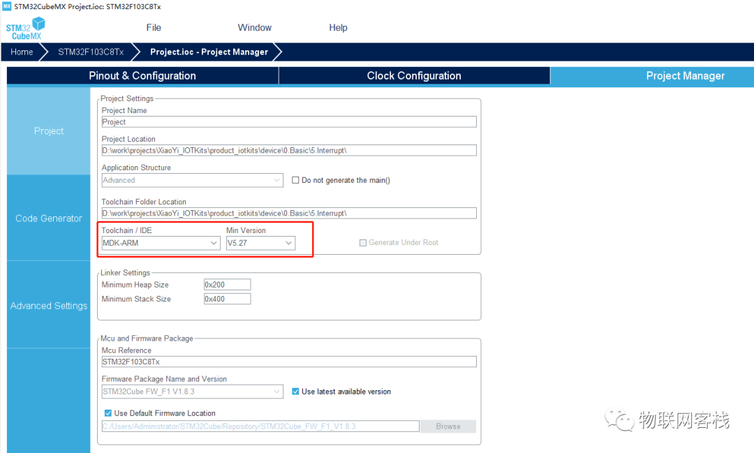
Switch to the Project Manager section, set the project name, project save directory, toolchain, etc., with parameters as shown in the figure below.
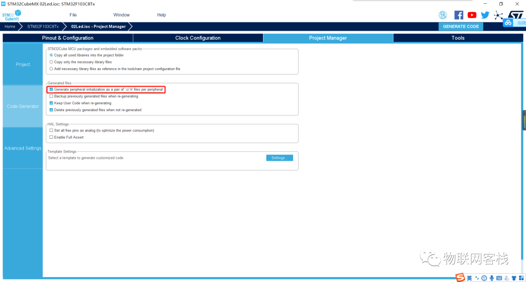
Click on the Code Generator on the left column, then check Generate peripheral initialization as a pair of ‘.c/.h’ files per peripheral. By checking this option, peripherals will be saved in a separate file instead of all in main.c.
2Function Description
(1) First, check the MX_GPIO_Init() function in gpio.c
void MX_GPIO_Init(void){ GPIO_InitTypeDef GPIO_InitStruct = {0}; /* GPIO Ports Clock Enable */ __HAL_RCC_GPIOC_CLK_ENABLE(); __HAL_RCC_GPIOD_CLK_ENABLE(); __HAL_RCC_GPIOB_CLK_ENABLE(); __HAL_RCC_GPIOA_CLK_ENABLE(); /*Configure GPIO pin Output Level */ HAL_GPIO_WritePin(GPIOC, GPIO_PIN_13, GPIO_PIN_RESET); /*Configure GPIO pin Output Level */ HAL_GPIO_WritePin(GPIOB, GPIO_PIN_12, GPIO_PIN_RESET); /*Configure GPIO pin : PC13 */ GPIO_InitStruct.Pin = GPIO_PIN_13; GPIO_InitStruct.Mode = GPIO_MODE_OUTPUT_PP; GPIO_InitStruct.Pull = GPIO_NOPULL; GPIO_InitStruct.Speed = GPIO_SPEED_FREQ_LOW; HAL_GPIO_Init(GPIOC, &GPIO_InitStruct); /*Configure GPIO pin : PB12 */ GPIO_InitStruct.Pin = GPIO_PIN_12; GPIO_InitStruct.Mode = GPIO_MODE_OUTPUT_PP; GPIO_InitStruct.Pull = GPIO_NOPULL; GPIO_InitStruct.Speed = GPIO_SPEED_FREQ_LOW; HAL_GPIO_Init(GPIOB, &GPIO_InitStruct); /*Configure GPIO pin : PB4 */ GPIO_InitStruct.Pin = GPIO_PIN_4; GPIO_InitStruct.Mode = GPIO_MODE_IT_RISING; GPIO_InitStruct.Pull = GPIO_NOPULL; HAL_GPIO_Init(GPIOB, &GPIO_InitStruct); /* EXTI interrupt init*/ HAL_NVIC_SetPriority(EXTI4_IRQn, 2, 0); HAL_NVIC_EnableIRQ(EXTI4_IRQn);}In the GPIO initialization function, first enable the GPIOB clock, then initialize PB12 and PC13 as output mode, and PB4 as input mode. The interrupt operation NVIC configures the interrupt priority and enables the EXTI4_IRQn interrupt. EXTI is the external interrupt/event controller, which manages a total of 20 interrupt/event lines, each of which corresponds to an edge detector that can be configured as an interrupt or event. The specific correspondence between the interrupt/event lines is as follows:
|
Interrupt/Event Line |
Description |
|
EXTI0 |
PA0~PI0 |
|
EXTI1 |
PA1~PA1 |
|
EXTI2 |
PA2~PA2 |
|
EXTI3 |
PA3~PA3 |
|
EXTI4 |
PA4~PA4 |
|
EXTI5 |
PA5~PA5 |
|
EXTI6 |
PA6~PA6 |
|
EXTI7 |
PA7~PA7 |
|
EXTI8 |
PA8~PA8 |
|
EXTI9 |
PA9~PA9 |
|
EXTI10 |
PA10~PA10 |
|
EXTI11 |
PA11~PA11 |
|
EXTI12 |
PA12~PA12 |
|
EXTI13 |
PA13~PA13 |
|
EXTI14 |
PA14~PA14 |
|
EXTI15 |
PA15~PA15 |
|
EXTI16 |
PVD output |
|
EXTI17 |
RTC alarm event |
|
EXTI18 |
USB wakeup event |
|
EXTI19 |
Ethernet wakeup event (only for interconnect) |
(2) Interrupt Handler Function
When an interrupt occurs, it will enter the corresponding void EXTI4_IRQHandler(void) function in the interrupt vector table mentioned above, which is in stm32f1xx_it.c.
/*** @brief This function handles EXTI line4 interrupt.*/void EXTI4_IRQHandler(void){ /* USER CODE BEGIN EXTI4_IRQn 0 */ /* USER CODE END EXTI4_IRQn 0 */ HAL_GPIO_EXTI_IRQHandler(GPIO_PIN_4); /* USER CODE BEGIN EXTI4_IRQn 1 */ /* USER CODE END EXTI4_IRQn 1 */}In stm32f1xx_hal_gpio.c, the definition of HAL_GPIO_EXTI_IRQHandler(uint16_t GPIO_Pin) is as follows:
/*** @brief This function handles EXTI interrupt request.* @param GPIO_Pin: Specifies the pins connected EXTI line* @retval None*/void HAL_GPIO_EXTI_IRQHandler(uint16_t GPIO_Pin){/* EXTI line interrupt detected */ if (__HAL_GPIO_EXTI_GET_IT(GPIO_Pin) != 0x00u) { __HAL_GPIO_EXTI_CLEAR_IT(GPIO_Pin); HAL_GPIO_EXTI_Callback(GPIO_Pin); }}/* @brief EXTI line detection callbacks.* @param GPIO_Pin: Specifies the pins connected EXTI line* @retval None*/__weak void HAL_GPIO_EXTI_Callback(uint16_t GPIO_Pin){/* Prevent unused argument(s) compilation warning */UNUSED(GPIO_Pin);/* NOTE: This function Should not be modified, when the callback is needed,the HAL_GPIO_EXTI_Callback could be implemented in the user file*/}When it is confirmed that external interrupt line 4 has occurred, the system will call the HAL_GPIO_EXIT_Callback(uint16_t GPIO_Pin) function. This function is a __weak function, and the user can redefine this function at the application layer. If the user forgets to define it, the system will not report an error but will enter this __weak function, doing nothing.
2Modify the Program
In gpio.c, redefine the void HAL_GPIO_EXTI_Callback(uint16_t GPIO_Pin) function.
volatile int key_flag= 0;void HAL_GPIO_EXTI_Callback(uint16_t GPIO_Pin){ // Key pressed key_flag = 1;}In main.c, based on the interrupt handler function flag, perform further processing. When the key is pressed, reset the key flag and toggle the LED.
/* USER CODE BEGIN 0 */extern volatile int key_flag;/* USER CODE END 0 */** * @brief The application entry point. * @retval int */int main(void){ /* USER CODE BEGIN 1 */ /* USER CODE END 1 */ /* MCU Configuration--------------------------------------------------------*/ /* Reset of all peripherals, Initializes the Flash interface and the Systick. */ HAL_Init(); /* USER CODE BEGIN Init */ /* USER CODE END Init */ /* Configure the system clock */ SystemClock_Config(); /* USER CODE BEGIN SysInit */ /* USER CODE END SysInit */ /* Initialize all configured peripherals */ MX_GPIO_Init(); /* USER CODE BEGIN 2 */ /* USER CODE END 2 */ /* Infinite loop */ /* USER CODE BEGIN WHILE */ while (1) { /* USER CODE END WHILE */ /* USER CODE BEGIN 3 */ if ( key_flag ) { HAL_GPIO_TogglePin(GPIOB, GPIO_PIN_12); key_flag = 0; } HAL_Delay(10); } /* USER CODE END 3 */}Download the program to the core board as in the previous section. You will see that each time the key is pressed, the red LED lights up or goes out.
If you have any questions during use, please join our QQ group for further communication.
QQ group: 906015840 (Note: IoT project communication)
Source code acquisition: Follow the public account, reply xiaoyi_stm32kits to obtain materials.
Hardware acquisition:
Mini-program to obtain hardware.
One leaf, one world, one leaf, one Bodhi.