
01
Overview
Disadvantages of Existing Technology:
-
The gear in the aircraft engine, as a key component for power transmission, can lead to fuel line issues and power interruptions if it fails, posing a serious risk to flight safety. Therefore, condition monitoring is particularly important. -
Current gear fault detection methods rely on vibration sensors, but aircraft engines operate in high-temperature and high-noise environments, which pose severe challenges to the vibration sensors, affecting their monitoring accuracy and reliability.
Highlights of the Article:
-
The research team developed a novel piezoelectric vibration sensor using PVDF, PI, and carbon nanotube (CNT) nanofiber membranes to enhance piezoelectric performance. By incorporating PI material, the impact of high temperatures on sensor performance was effectively mitigated, resulting in only a 15% performance drop at 80℃.
-
This sensor maintains high sensitivity and stability in high-noise and high-temperature environments, accurately monitoring changes in vibration frequency and acceleration.
-
Combined with deep learning algorithms, the sensor achieves an impressive fault mode recognition accuracy of 96.3% for gear faults.
Application Scenarios:
-
Intelligent Health Management of Aircraft Engines: The sensor and fault recognition system can effectively monitor the operational status of engine gears, suitable for fault diagnosis and prevention in aircraft engines.
-
Intelligent Operation and Maintenance Systems: The developed digital twin system provides an innovative solution for real-time status monitoring and intelligent maintenance of aircraft engines, with broad application prospects.
Conclusion:
This research proposes a novel piezoelectric vibration sensor suitable for high-temperature and high-noise environments, effectively enhancing the accuracy and timeliness of gear fault recognition in aircraft engines through the integration of digital twin and deep learning technologies. This offers new ideas for the intelligent health management of aircraft engines, potentially improving flight safety.
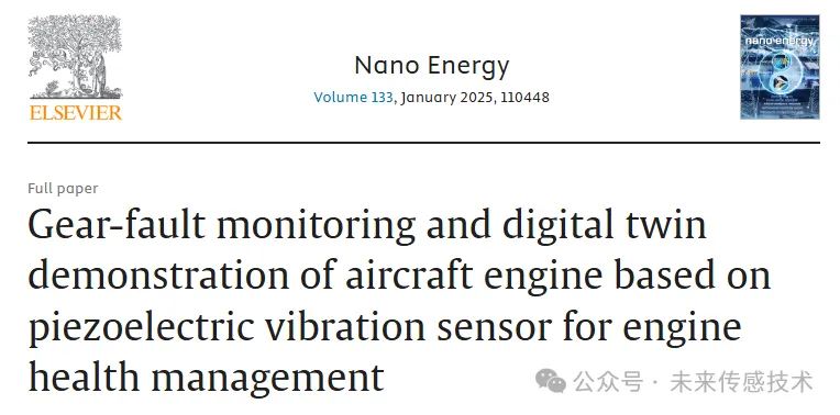 Article Name: Gear-fault monitoring and digital twin demonstration of aircraft engine based on piezoelectric vibration sensor for engine health management
Journal: Nano Energy (IF=16.8)
Article DOI:
https://doi.org/10.1016/j.nanoen.2024.110448
Corresponding Authors: Associate Professor Zhang Yang from Taiyuan University of Science and Technology and Professor Zhang Hulin from Taiyuan University of Technology
Authors: Doctoral student Hu Yijian from Taiyuan University of Science and Technology as the first author, with Lecturer Guo Rui as co-first author
02
Illustrated Introduction
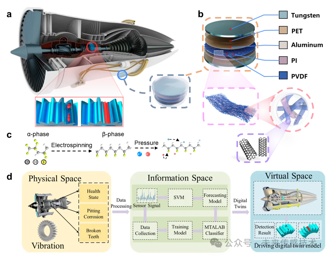
Figure 1. Design of PVDF-PI nanofiber membrane piezoelectric vibration sensor for aircraft engine gear fault monitoring. (a) Schematic of the piezoelectric vibration sensor in aircraft engine gear fault monitoring. (b) Structure diagram of the vibration sensor. (c) Conformational change model of PVDF during electrospinning. (d) Digital twin system framework for aircraft engine fault monitoring.
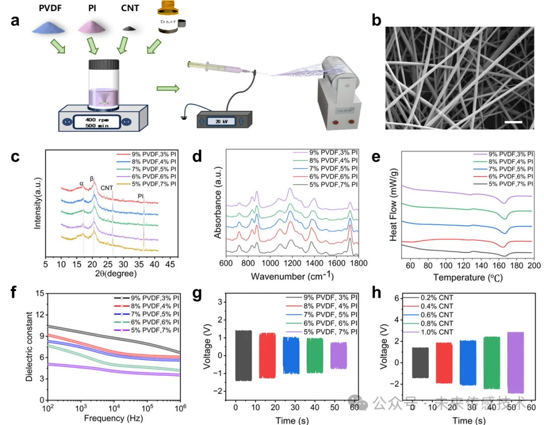
Figure 2. Fabrication and characterization of PVDF-PI nanofiber membranes. (a) Electrospinning method for preparing nanofiber membranes. (b) Scanning electron microscope (SEM) images of nanofiber membranes with 9 wt% PVDF and 3 wt% PI ratio; scale bar, 2 μm. (c) X-ray diffraction (XRD) patterns of PVDF-PI nanofiber membranes with different PVDF and PI ratios. (d) Fourier-transform infrared spectroscopy (FTIR) of PVDF-PI nanofiber membranes with different PVDF and PI ratios. (e) Differential scanning calorimetry (DSC) analysis of PVDF-PI nanofiber membranes with different PVDF and PI ratios. (f) Dielectric constants of nanofiber membranes with different ratios. (g) Output voltage of sensors prepared with different PVDF and PI ratios. (h) Output voltage of sensors prepared with different carbon nanotube (CNT) ratios.
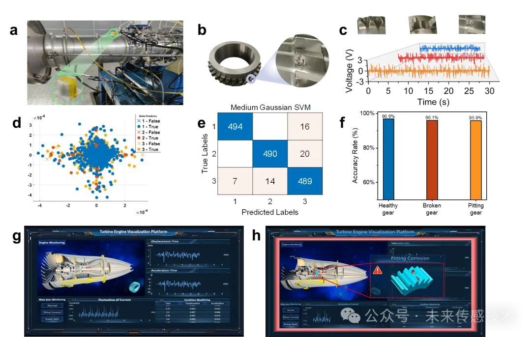
Figure 3. Electrical performance characterization of the vibration sensor. (a) Simulated potential distribution of nanofiber membranes containing 1 wt% CNTs. (b) Output voltage of the sensor under different contact pressures. (c) Output voltage of the sensor under different diameters of nanofiber membranes. (d) Output voltage of the sensor under different vibration frequencies and accelerations; inset: output voltage in the high-frequency range. (e) Output current of the sensor under different vibration frequencies and accelerations; inset: output current in the high-frequency range. (f) Output voltage of the sensor with/without sponge. (g) Output voltage of the sensor under 80℃ with/without PI. (h) Output voltage of the sensor under different temperatures with 3 wt% PI. (i) Electrical output stability of the sensor after 8000 seconds.

Figure 4. Gear fault identification and digital twin demonstration for aircraft engines. (a) Testing platform for aircraft engines equipped with piezoelectric vibration sensors. (b) Image of gear pitting. (c) Typical vibration signals of healthy gears, damaged gears, and pitted gears. (d) Scatter plot of gear state pattern feature distribution. (e) Confusion matrix of gear state prediction. (f) Accuracy of gear state pattern recognition. (g) Digital twin system for gear monitoring and fault identification. (h) Digital twin system providing alerts for pitted gears.
03
References
https://doi.org/10.1016/j.nanoen.2024.110448
For submissions, reprints, or collaborations, please contact WeChat:MatResFron001

Feel free to leave comments and share your views.Support the authors by clicking the “like” button belowand “see it”↓↓↓