The powerful features and low price of the Pico have attracted the attention of makers around the world. This article aims to introduce you to this little gadget.
The original article comes from DroneBot Workshop, and the person in charge is a very kind old man. Those who can should go to YouTube to follow him.
This article uses MicroPython to program the Raspberry Pi Pico, so let’s see what this thirty-dollar microcontroller can do.
Introduction
The release of the microcontroller by the Raspberry Pi Foundation is already big news, as before this, the world’s most popular single-board computer manufacturer had never expressed interest in microcontrollers.
Not only the announcement of the Raspberry Pi Pico was surprising, but this time Raspberry Pi also designed a new chip by themselves. They did not support designs based on ESP32 or SAMD21 based on existing code, but chose to create their own microcontroller.
So when it comes to Pico, we are all beginners.
The Raspberry Pi Foundation has also released a lot of technical documentation on their official website, along with a manual called “Get Started with MicroPython on Raspberry Pi Pico”. It is available in both printed and PDF versions for download.
In addition, there is currently no deeper information about the Pico. However, as time goes by, this situation will soon change, as Raspberry Pi has authorized other manufacturers, including Adafruit, to use the RP2040 chip in their designs. In due course, this will bring us more code and development tools.
Let’s first try connecting a bunch of things to the Pico and see what interesting things happen!
Raspberry Pi Pico
The Pico is a small board, about the size of an Arduino Nano. Like all Raspberry Pis, the packaging is very simple, just a Pico inside a plastic wrapper, and the plastic wrapper itself is cut from strips of packaging, very reminiscent of the shrimp chips or candy wrappers we used to eat as kids.
Take a Look at the Pico Board
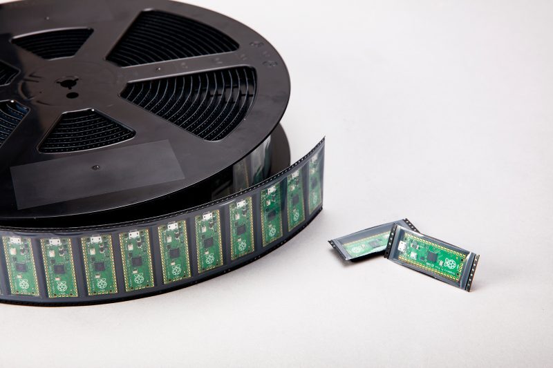
The board we bought only comes as a bare board, nothing more, which is very environmentally friendly.
The bare board does not come with pins, and you need to solder them yourself. It is a well-made circuit board that can also be used as SMD components soldered directly onto a printed circuit board.
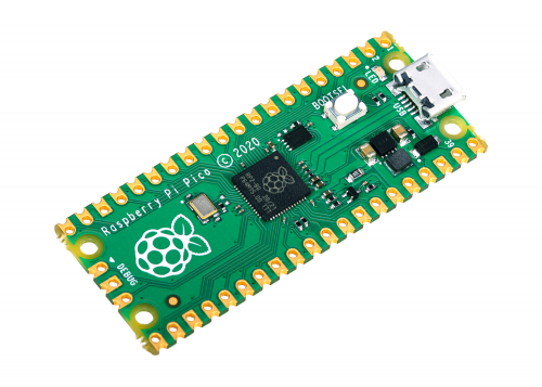
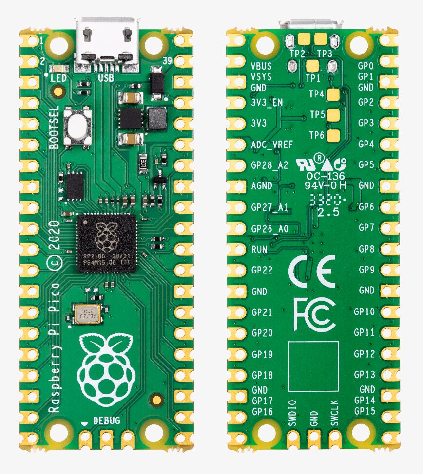
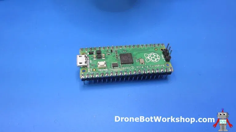
Top View
From the top, the Pico looks like this.
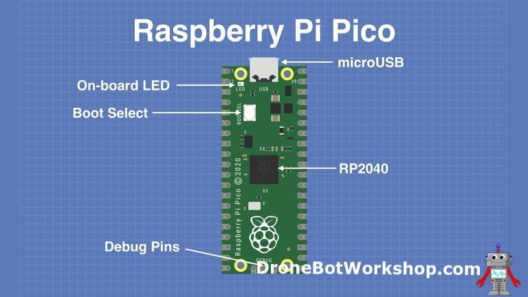
The main feature on the board is the microUSB connector at one end. It is used for both communication and powering the Pico.
Next to the microUSB connector is an onboard LED that is internally connected to GPIO pin 25.
It is worth noting that this is the only LED on the entire Pico board.
The power button is installed a little lower than the LED, and it allows you to change the boot mode of the Pico, so you can load MicroPython on it and perform drag-and-drop programming.
On the bottom of the board, you will see three connection points, which are used for serial debug options, but we are just getting started today, so we won’t discuss this for now; advanced developers may be more interested.
In the center of the board is the “brain” of the entire board—RP2040 MCU, and we will study its functions shortly.
Ground Pins
There are several ground pins on the board, 8 ground pins plus one additional ground pin on the 3-pin debug connector.
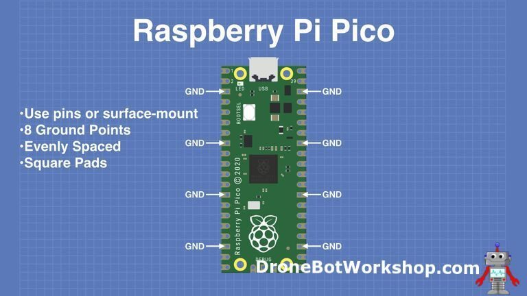
These pins are easy to find, they are evenly spaced and square, unlike the round ones found in other connections.
One of the ground pins located at pin 33 is also designated as an analog ground.
Power Pins
The Pico is a 3.3V logic device, but due to its built-in voltage converter and regulator, it can be powered by a range of voltages.
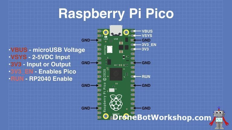
All power-related pins are grouped together, close to the microUSB connector.
-
VBUS – This is the power from the microUSB bus, 5V. If the Pico is not powered by the microUSB connector, there will be no output here. -
VSYS – This is the input voltage, ranging from 2 to 5V. The onboard voltage converter will convert it to 3.3V for the Pico. -
3V3 – This is the 3.3V output from the Pico’s internal regulator. It can be used to power other components as long as the load is kept below 300mA.
There are also several inputs that allow you to control the power to the Pico.
-
3V3_EN – You can use this input to disable the Pico’s internal voltage regulator, turning off the Pico and any components powered by it.
-
RUN – Can enable or disable the RP2040 microcontroller, or reset it.
GPIO Pins
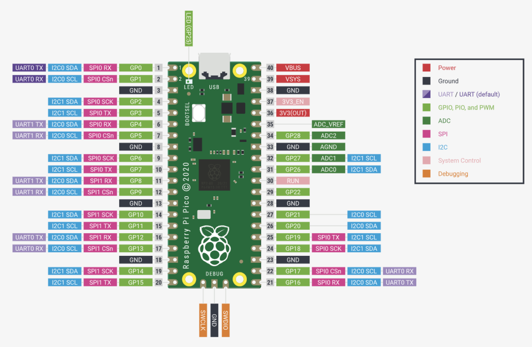
The Raspberry Pi Pico board has 26 exposed GPIO connections.
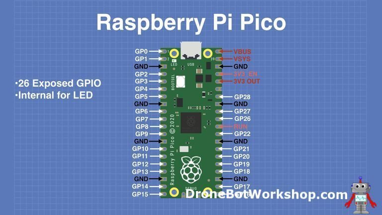
The arrangement is nice, with a “gap” between GPIO 22 and GPIO 26 (these “missing” pins are used internally).
These pins have multiple functions, and you can configure up to 16 pins for PWM.
There are two I2C buses, two UARTs, and two SPI buses, which can be configured to use various GPIO pins.
Analog Pins
The Pico has three analog-to-digital converters, plus one internal converter for the onboard temperature sensor.
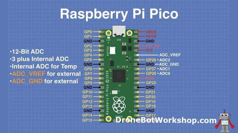
The resolution of the ADC is 12 bits.
You can also provide an external precision voltage reference on the ADC_VREF pin. One of the ground points, namely the ADC_GND on pin 33, is used as the ground point for that reference.
RP2040 Microcontroller
The Raspberry Pi Pico is designed around the foundation’s new RP2040 microcontroller. Here are its specifications:
-
Dual-core 32-bit ARM Cortex-M0+ processor -
Running at 48MHz, but can be overclocked to 133MHz. -
30 GPIO pins (26 exposed) -
Supports USB host or device mode -
8 programmable I/O (PIO) state machines
The RP2040 can support up to 16MB of external flash memory, but only 4MB is present in the Pico.
The Raspberry Pi Foundation has many plans for this chip and has already authorized many other manufacturers.
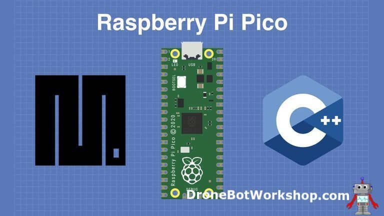
Programming the Pico
You can get started with the Pico using one of two programming languages.
-
MicroPython – An interpreted language specifically designed for microcontrollers. -
C++ – Many microcontroller users are familiar with C++, as it is used on Arduino and ESP32 boards.
While I am eager to use C++ with the Pico to squeeze every bit of performance out of it, I decided to go with MicroPython like most people. During this early development phase, the tools for C++ are still being finalized, looking forward to the Pico becoming part of the PlatformIO and Arduino IDE board series.
Getting Started with the Pico
When we get the Pico board, it is packaged in a plastic carrier, with no extra parts.
Unless you plan to surface mount the Pico, or your only goal is just to light an LED, we all need some pins.
The Pico has 40 pins, 20 on each side. Three additional pins are used for the debug port.
The standard male header pins have 40 pins, so you can cut one of the pin headers in half to use as the Pico’s pins. If you want to install pins on the debug connector, you will need another 3-pin male header, which can be straight or 90 degrees.
Soldering a Pico
Before we start programming the Pico, we need to do some soldering! In addition to the male header pins, we also need a suitable soldering iron and some solder.
The tip of the soldering iron needs to be fine, and we also need a clean sponge and a stand.
Additionally, we need to find a way to hold the Pico in place while soldering its pins, as they need to be installed at a precise 90-degree angle to fit into a breadboard.
Many experiments use a breadboard to hold the pins, although this method works, it can potentially damage the breadboard due to heat or solder splatter.
So the best solution is to use an old breadboard as a pin holder.
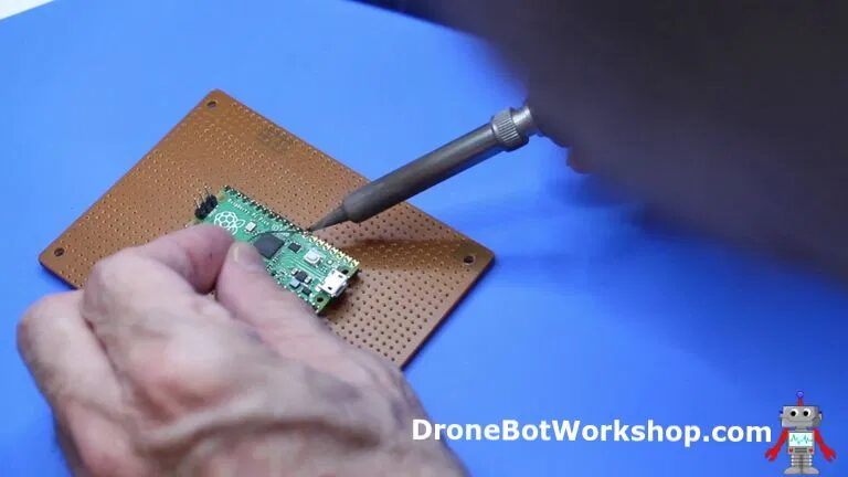
I personally like to use a few cheap perfboards, perforated experimental boards. When I say “cheap,” I mean single-sided ones without plated holes, with only one side being bare copper.
Two pieces of this are great for holding the pins, and I often use this when needing to solder a small module or microcontroller.
Heat the soldering iron to a certain temperature, then heat the connection between the pin and the pad, applying solder on the opposite side, being careful not to apply solder directly to the soldering iron. Heat the component, not the solder.
If you want to solder the 3-pin debug connector (which is optional), you may want to do this first. The orientation of these pins is opposite to that of the GPIO pins. I used a small notepad to hold the circuit board because the debug connector does not align with the GPIO pins on the grid.
Then it’s time to solder the 40 pins, 20 at a time! It really doesn’t take too long, just use as much solder as possible, avoiding solder bridges, and check afterwards.
Cleaning the Pico After Soldering
I like to clean my PCBs after soldering to remove the flux and resin from the solder core. It appears as brown stains around the solder joints.
This step is entirely optional, as the flux and resin do not adversely affect the operation or lifespan of the components. It just looks better!

If you want to clone your board, you need some PCB cleaning solution or Flux Remover. Since it often leaves a bit of residue, I use isopropanol to clean.
PCB cleaning solution can be purchased online. Isopropanol can be found at local pharmacies, just make sure to buy the pure alcohol and water mixture (70%), and avoid scented ones.
I work with an old toothbrush and some plastic containers in a basin. Remember to prepare a mask, gloves, and goggles.

I scrub the pins with the toothbrush dipped in PCB cleaning solution, and then rinse with the toothbrush dipped in isopropanol.
Let the board air dry naturally, or you can use an air hose, and then we will have a shiny new Pico!
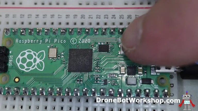
Pico and Thonny IDE
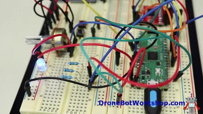
Now that the pins of the Pico are connected, we can start experimenting with it.
I recommend placing it on a breadboard to prepare for our upcoming experiments.
While there are many IDEs to choose from to work with our new Pico, my recommendation is to use the Thonny IDE recommended by Raspberry Pi.
Thonny IDE
Thonny calls itself the “Python IDE for Beginners,” and it is available for Windows, Mac OSX, and Linux.
It is also part of the Raspberry Pi OS (formerly Raspbian).
I will be using Thonny IDE on the Raspberry Pi OS running on an 8GB Raspberry Pi 4 as my development platform for today’s experiments. Of course, you can use any platform that can run Thonny, but I want it to run within the Raspberry Pi family—plus, since Thonny is already installed on the newly built Raspberry Pi OS, it is very easy to get started.
Starting and Installing MicroPython
The first thing we need to do is install MicroPython on the Pico.
Connect the microUSB to the Pico and prepare to plug the other end into the computer. Before plugging in, press the Boot Select button on the Pico.
Press and hold the BOOTSEL button while plugging the Pico into the USB port of the computer. Hold the BOOTSEL button for a few seconds and then release it.
You should see a new drive available on your computer, and the information will look different depending on the operating system you are using, but it is similar to the information you get when you plug a USB flash drive into your computer.
Open the new “drive,” and you will see a folder named RPI-RP2. Inside this drive, you will see several files, one of which is a web document index.htm.
Click on that web file, and your browser will open, redirecting you to the Raspberry Pi Pico getting started page.
Click on the MicroPython getting started tab. You will see a link to download a UF2 file, which is the downloadable MicroPython file. Download this file to your computer.
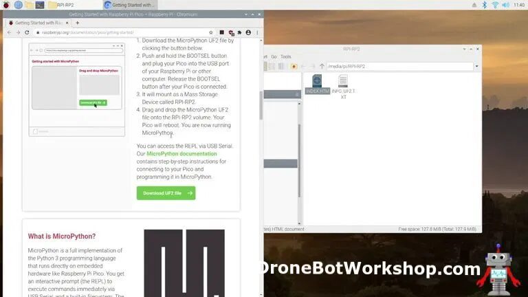
Now drag the downloaded file into the Pico’s RPI-RP2 folder. Once you do this, the folder will disappear and the Pico will boot into MicroPython mode.
Configuring Thonny IDE
With the Pico still connected, open Thonny IDE. If you are using Raspberry Pi OS like me, you will find Thonny under the programming tools menu.
Once Thonny opens, look at the status bar in the lower right corner; it may show a version of Python. This is the current version of Python running on your computer, which is not important for our experiments.
Click on that message, and a dropdown menu should appear with other environments to choose from. One of them should be MicroPython (Raspberry Pi Pico). Select that one.
You will notice a new shell opens at the bottom, where you should see some text indicating that you are connected to the Pico.
It’s time to start programming!
Shell Testing
The shell is Pico’s “command line” where you can execute code directly.
A simple test is to enter the following (this is also a good way to check if you are correctly connected to the Pico), and then press Enter.
print("Hello World")
You should see “Hello World” printed in the shell, which is of course what you told the Pico to do.
Script Testing
Of course, you won’t be entering your programs directly in the shell, because once you execute a program, they disappear, and for any reasonably sized program, it is also inconvenient.
You will be entering your program in the editor, which is the large text area dominating the screen above the shell in Thonny IDE.
In this editor, enter the same text as before, greeting the programming world with a nice “Hello”.
Click the “Run” button (the green one with an arrow), and the system will prompt you to save the program first. You can choose to save it on your local computer or on the Pico; try saving it on the Pico. Give your program a name with a “.py” extension, such as “hello.py”.
The program will be saved and run, and you will see the greeting “Hello World” in the shell. You can click the “Run” button again to see it again, and click it once more.
So now you know how to write and save MicroPython programs, and we can start our experiments!
Using LEDs and Switches
Basic digital I/O functionality can be easily demonstrated with LEDs and switches, which is exactly how we will start our Pico adventure.
But pay attention to how we wire the switch; we will do it differently.
RGB LED
The simplest output device might be an LED. When sufficient current is applied in the correct direction, this output device works. While simple, it can illustrate I/O techniques that can be applied to other devices such as relays or transistors.
I will be using a common-cathode RGB LED, but you can also replace it with three discrete LEDs. Either way, you will also need three current-limiting resistors; I used 330-ohm resistors in my experiment.
If you choose to use an RGB LED like I do, make sure to buy a standard RGB LED and not a programmable one.
Button Switch
This is the simplest input device. I am using a pair of momentary normally-open button switches.
One red and one black, but otherwise the same.
We are again using a simple input device to test the I/O capabilities of our little Pico. We will wire the two switches in different ways to make it more interesting, and we will not use any pull-up or pull-down resistors.
Connecting LEDs and Switches
Here is our connection diagram for the LEDs and switches; remember, if you do not have a common-cathode RGB LED, you can use three individual LEDs.
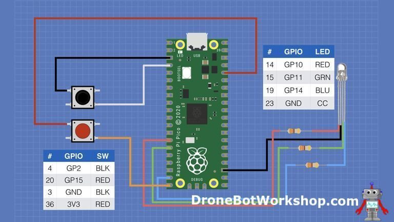
Note how the wiring of the two switches is different.
The black button switch connects one side to the Pico’s GPIO pin and the other side to ground.
The red switch is the opposite; one side connects to the GPIO pin, and the other side connects to 3.3 volts, which is the Pico’s working voltage and logic voltage.
Classic Project – Blinking Lights
The first experiment we will do is a variant of our own Arduino “Blink” sketch. Yes, technically we have already seen how to blink the onboard LED, but now that we have an RGB LED under our control, we can certainly find another way to light it up!
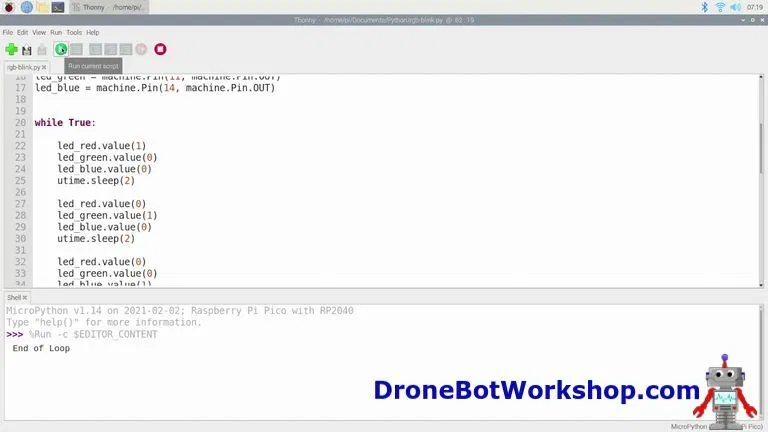
Open the following code in Thonny.
# Raspberry Pi Pico RGB Blink
# rgb-blink.py

# RED LED - Pico GPIO 10 - Pin 14
# GREEN LED - Pico GPIO 11 - Pin 15
# BLUE LED - Pico GPIO 14 - Pin 19

# DroneBot Workshop 2021
# https://dronebotworkshop.com

import machine
import utime

led_red = machine.Pin(10, machine.Pin.OUT)
led_green = machine.Pin(11, machine.Pin.OUT)
led_blue = machine.Pin(14, machine.Pin.OUT)

while True:

    led_red.value(1)
    led_green.value(0)
    led_blue.value(0)
    utime.sleep(2)

    led_red.value(0)
    led_green.value(1)
    led_blue.value(0)
    utime.sleep(2)

    led_red.value(0)
    led_green.value(0)
    led_blue.value(1)
    utime.sleep(2)

    led_red.value(1)
    led_green.value(1)
    led_blue.value(0)
    utime.sleep(2)

    led_red.value(1)
    led_green.value(0)
    led_blue.value(1)
    utime.sleep(2)

    led_red.value(0)
    led_green.value(1)
    led_blue.value(1)
    utime.sleep(3)

    led_red.value(1)
    led_green.value(1)
    led_blue.value(1)
    utime.sleep(2)

    print("End of Loop")

    led_red.value(0)
    led_green.value(0)
    led_blue.value(0)
    utime.sleep(2)
This is a simple script that can certainly be improved, but it illustrates our point well.
We first import the machine and utime libraries. You will find that any activity involving I/O ports requires the use of machine, and whenever we want to use time functions, we need to use utime.
Then we define the connections of the three LED elements; note that they are represented by GPIO numbers rather than the physical pin numbers on the Pico. All these pins are defined as machine.Pin.OUT, which means these pins are now set as output pins.
The while True condition is similar to the Loop in Arduino sketches, and the code here runs continuously.
In this section, we address the LEDs and set them to on (value of 1) or off (value of 0). We go through a sequence, and in the last sequence, we print to the console.
Then we do it all over again.
Load the script onto the Pico and watch the LEDs; you should see a colorful blinking.
Switch Testing
Our next script is a very basic test of the two switches, and we will wire them in a somewhat strange way.
The first strange thing you will notice is that their wiring is different; the black switch connects the input to ground, while the red switch connects the input to 3.3 volts for a logic HIGH.
Another interesting thing is that neither of these switches uses pull-up or pull-down resistors; they clearly need these resistors—the black switch needs a pull-up, and the red switch needs a pull-down to work correctly.
We will add the required resistors in the code!
# Raspberry Pi Pico Switch Test
# switchtest.py

# RED BUTTON - Pico GPIO 15 - Pin 20
# BLACK BUTTON - Pico GPIO 2 - Pin 4

# DroneBot Workshop 2021
# https://dronebotworkshop.com

import machine
import utime

button_red = machine.Pin(15, machine.Pin.IN, machine.Pin.PULL_DOWN)
button_black = machine.Pin(2, machine.Pin.IN, machine.Pin.PULL_UP)

while True:

    if button_red.value() == 1:
        print("Red")

    if button_black.value() == 0:
        print("Black")

    utime.sleep(0.25)
Note the syntax on the lines defining the buttons; you will see how they are defined as Inputs and how the pull-down and pull-up resistors were added.
In the while True: loop, you will also notice that we are monitoring different conditions; the red switch triggers a HIGH input, while the black switch triggers a LOW.
The last small time delay is a simple form of debouncing, and if you like, you can experiment with this value.
This script will print all the results to the console, so pay attention when you press the buttons.
Interrupts and Toggles
The next experiment introduces a couple of useful concepts. The first, and arguably the most important of these two concepts, is “interrupts”.
Interrupts
Interrupts are, as their name suggests, events that “interrupt” the normal flow of the program. In our case, we are dealing with external hardware interrupts, which means that a signal or state change needs to be handled before the program can continue running.
On the Pico, we create an interrupt in the following way.
-
We define a pin as an “interrupt input,” and we define that a change of state at that point is considered an interrupt. On the Pico, we can use any GPIO pin for this, and we can define multiple pins.
-
We create an “interrupt handler” function that we want to run when the interrupt is detected.
-
We pair the “interrupt handler” with the “interrupt input”.
Now, whenever the interrupt input condition occurs, the Pico will stop whatever it is doing and execute the “interrupt handler”. It will then resume back to where it left off.
Toggles
While not as fundamental as interrupts, toggles are still very useful. A “toggle” simply reverses the output state on the Pico.
So if the output is HIGH, applying a toggle will change it to LOW.
We do not need to know the current state of the output; we just need to know that when we apply a toggle, it will change to the opposite state.
Naturally, this is an ideal function to write another Blink program, so we will do just that. Only our Blink program will have the risk of being interrupted!
# Raspberry Pi Pico Interrupt & Toggle Demo
# interrrupt-toggle-demo.py

# RED LED - Pico GPIO 10 - Pin 14
# GREEN LED - Pico GPIO 11 - Pin 15

# RED BUTTON - Pico GPIO 15 - Pin 20

# DroneBot Workshop 2021
# https://dronebotworkshop.com

import machine
import utime

led_red = machine.Pin(10, machine.Pin.OUT)
led_green = machine.Pin(11, machine.Pin.OUT)

led_red.value(0)
led_green.value(0)

button_red = machine.Pin(15, machine.Pin.IN, machine.Pin.PULL_DOWN)

def int_handler(pin):
    button_red.irq(handler=None)
    print("Interrupt Detected!")
    led_red.value(1)
    led_green.value(0)
    utime.sleep(4)
    led_red.value(0)
    button_red.irq(handler=int_handler)

button_red.irq(trigger=machine.Pin.IRQ_RISING, handler=int_handler)

while True:

     led_green.toggle()
     utime.sleep(2)
In this MicroPython script, we will blink the green part of our RGB LED using a switch to change its state. Under normal operation, the LED state will toggle every two seconds.
However, we can interrupt the blinking by pressing the red button. This will trigger an interrupt, which will turn off the green LED and turn on the red one. It will stay on for four seconds, after which the program control will be restored so we can continue with the green blinking.
We start our script by importing the machine and utime libraries, just like before.
The definitions of the LED segments and the red button are the same as in previous scripts. The LEDs are turned off at the start of the program.
Then we define a function, which is our interrupt handler, called “int_handler”. In this function, we do the following:
-
Disable the interrupt so that we do not have multiple interrupts. -
Print “Interrupt Detected” to the Shell. -
Turn on the red LED segment. -
Turn off the green LED segment. -
Sleep for four seconds. -
Turn off the red segment. -
Re-enable the interrupt. -
Exit.
The line after the handler function binds the interrupt to the pin we defined as the input for the red button. It is important to note that it specifies “IRQ_RISING,” which means that if the input rises from 0 (ground) to 1 (3.3 volts), it will trigger an interrupt. This aligns with how we wired the red button.
In the True loop, we simply use the “toggle” function available on any GPIO pin defined as output to blink the LED.

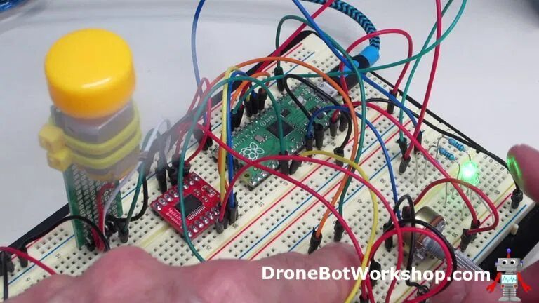
Send it to the Pico and observe the RGB LED; it should start blinking green. Watch for a while, then press the red button. The LED should turn red, and the Shell should display “Interrupt Detected”. After four seconds, the green blinking will resume.
Switch and LED Demonstration
Since we’ve been studying switches and LEDs, let’s combine them and write a simple script.
# Raspberry Pi Pico Switch & RGB LED Demo
# switch-led-demo.py

# RED LED - Pico GPIO 10 - Pin 14
# GREEN LED - Pico GPIO 11 - Pin 15
# BLUE LED - Pico GPIO 14 - Pin 19

# BLACK BUTTON - Pico GPIO 2 - Pin 4

# DroneBot Workshop 2021
# https://dronebotworkshop.com

import machine
import utime

led_red = machine.Pin(10, machine.Pin.OUT)
led_green = machine.Pin(11, machine.Pin.OUT)
led_blue = machine.Pin(14, machine.Pin.OUT)

led_red.value(0)
led_green.value(0)
led_blue.value(0)

button_black = machine.Pin(2, machine.Pin.IN, machine.Pin.PULL_UP)

while True:

    if button_black.value() == 0:

            led_red.value(1)
            led_green.value(0)
            led_blue.value(0)
            utime.sleep(1)

            led_red.value(0)
            led_green.value(1)
            led_blue.value(0)
            utime.sleep(1)

            led_red.value(0)
            led_green.value(0)
            led_blue.value(1)
            utime.sleep(1)

            led_red.value(0)
            led_green.value(0)
            led_blue.value(0)
This is quite simple, and everyone should now be familiar with its operation. We use the machine library functions to define the RGB LED and the black button.
Remember, the black button is defined as a pull-up to keep it HIGH, and when the button is pressed, it will go LOW because the other side is connected to ground.
So in the True loop, we look for a value of “0” to indicate that the button has been pressed. Once we detect this condition, we cycle through the colors of the LED segments.
As I said, this is a simple thing.
Analog Input Testing
Now let’s talk about analog inputs.
The Raspberry Pi Pico has three analog inputs, all with a 12-bit resolution.
The three inputs are as follows:
-
GPIO 26 – ADC0 (Pin 31) -
GPIO 27 – ADC1 (Pin 32) -
GPIO 28 – ADC2 (Pin 34)
There is also a fourth ADC for the internal temperature sensor.
Connecting a Potentiometer
In our test, we will use a potentiometer to present a variable voltage at the analog input, and then we will read that voltage. We will use ADC0 as our potentiometer input, but you can also use one of the other two.
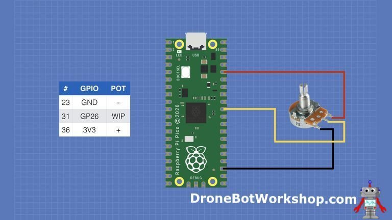
Note that while I show pin 23 as ground, this is just for convenience, and you can use any Pico ground pin. There is also a special analog ground at pin 33 that you can use. On my breadboard, I connected pin 33 to some other ground pins.
Potentiometer Readings
The first experiment we will do is simply read the value we get at the analog input, which should fluctuate based on the position of our potentiometer.
# Raspberry Pi Pico Analog Input Test
# analog-input.py

# POT - Pico GPIO 26 ADC0 - Pin 32

# DroneBot Workshop 2021
# https://dronebotworkshop.com

import machine
import utime

potentiometer = machine.ADC(26)

while True:
    print(potentiometer.read_u16())
    utime.sleep(2)
This is a simple script, as usual, first importing the machine library for GPIO operations and the utime library for time functions.
Then we define our potentiometer connection. Note how we use “ADC” to indicate that we want to use GPIO pin 26 as an analog input. Of course, this only applies to the three GPIO pins capable of analog input.
In the True loop, we simply print the value obtained from the potentiometer and then wait a few seconds before doing it again.
It is important to note that the value we get using the “read_u16” function is of type an unsigned 16-bit integer. This means it will vary between 0 and 65,535, rather than the 4095 you might expect from a 12-bit ADC.
This might seem odd, but as we will see in the next script, being able to pass values with the same numerical data type is actually useful.
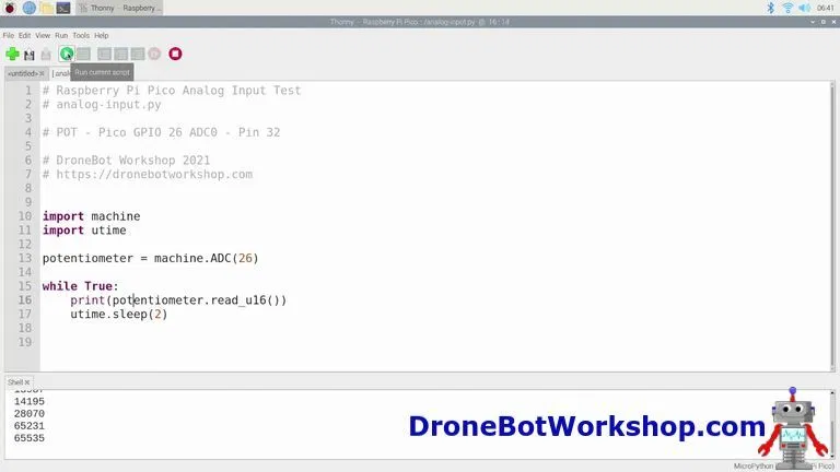
Run the script and watch the shell; you should see the values there change as you move the potentiometer shaft.
LED PWM Control
Let’s build on the previous script and use the output from the potentiometer to control the brightness of an LED.
Of course, we will use PWM for control, and this task is very simple in MicroPython.
# Raspberry Pi Pico LED PWM Test
# led-pwm.py

# POT - Pico GPIO 26 ADC0 - Pin 32

# RED LED - Pico GPIO 10 - Pin 14

# DroneBot Workshop 2021
# https://dronebotworkshop.com

import machine
import utime

led_red = machine.PWM(machine.Pin(10))
potentiometer = machine.ADC(26)

led_red.freq(1000)

while True:
    led_red.duty_u16(potentiometer.read_u16())
One key item to note in this script is how we define “led_red”. We define it as “PWM” instead of output.
The definition of the potentiometer is exactly the same as in the previous script.
Now that we have given the output the properties of “PWM,” it inherits many other parameters. One of these is the PWM frequency, which we set to 1000 Hz.
In the true loop, we continuously get the unsigned 16-bit value from the potentiometer and pass it to the LED’s duty cycle, conveniently specified as an unsigned 16-bit integer.
This illustrates the value of keeping both in the same numbering scheme, avoiding the need to map the analog value, which is really 0 to 4095, to a duty cycle, which is really 0 to 100.
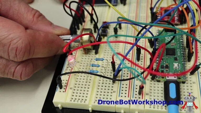
Run the program, and you should be able to smoothly control the brightness of the red LED segment.
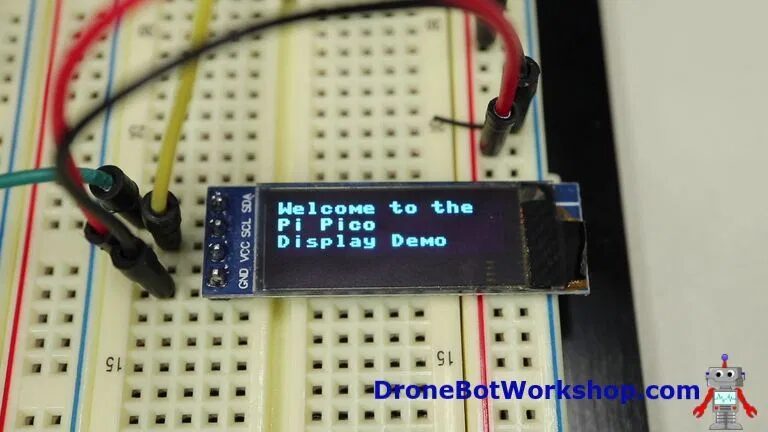
Adding a Display
The next experiment we will do is to connect an OLED display to our Pico and, of course, print something on it.
We will be using an I2C display, so we will also see how the Pico works with I2C connections. Remember, the Pico has two I2C buses.
Our OLED is a standard 1602 type OLED display, which is available everywhere. If you prefer, you can use a display with a different size than mine; just change the size in the code.
Here is how we will connect these things, with just four wires.
Our display requires a library that we can install using the Thonny IDE. You may find it easier in full menu mode than in basic mode, but both ways work.
-
Click on the “Tools” menu -
Click on “Manage Packages” -
Search for “ssd1306” -
Find “ssd1306.py” and install it.
Now that we have installed the library, we can look at a demo script for the OLED display.
# Raspberry Pi Pico OLED Display Test
# Uses ssd1306 module
# display-ssd1306-test.py

# DroneBot Workshop 2021
# https://dronebotworkshop.com

import machine
import utime

sda=machine.Pin(20)
scl=machine.Pin(21)

i2c=machine.I2C(0, sda=sda, scl=scl, freq=400000)

from ssd1306 import SSD1306_I2C
oled = SSD1306_I2C(128, 32, i2c)


print(i2c.scan())

oled.text('Welcome to the', 0, 0)
oled.text('Pi Pico', 0, 10)
oled.text('Display Demo', 0, 20)
oled.show()
utime.sleep(4)

oled.fill(1)
oled.show()
utime.sleep(2)
oled.fill(0)
oled.show()

while True:
    oled.text("Hello World",0,0)
    for i in range (0, 164):
        oled.scroll(1,0)
        oled.show()
        utime.sleep(0.01)
Our OLED display is an I2C device, so you will notice that at the beginning of the script, we define two GPIO pins as SDA (GPIO 20) and SCL (GPIO 21).
The Pico has two I2C buses, and you can use several different GPIO pins to connect them. But they are not just any pins; for example, certain pins are designated as SDA for bus 0, and only they can be used for SDA bus 0.
Then we define an I2C connection using the machine library’s I2C function. We need to provide the following parameters.
-
I2C bus number, which in our case is 0. -
SDA pin -
SCL pin -
I2C bus frequency—400KHz in our case.
Then we add the OLED library and create an I2C OLED object. We pass the size parameters and the I2C connection information to it.
Note that we do not pass the I2C address. The SD1306 OLED display has a fixed I2C address, so we do not need to specify it.
However, I added a line here that is unrelated to the display but allows you to scan the I2C bus and print the addresses it finds. Note that what is printed in the Shell is decimal, not hexadecimal, which you might be more accustomed to seeing.
Back to the OLED script!
We start printing a few lines of text on the display. Note how we specify the pixel position where each line starts.
In reality, we are not directly printing to the display; we are sending data to a buffer. The line oled.show() transfers that buffer’s data to the display.
After printing the welcome message and holding it for four seconds, we execute oled.fill(1). This will turn on every pixel in the display, or more accurately, every pixel in the buffer. We then do a oled.show() to display the fill.
We hold the fill on the display for two seconds, then execute oled.fill(0), which will turn off every pixel in the display when we show it.
Now we enter the True loop.
We again input some text, the classic “Hello World”. But we do not do a “show” to display it; instead, we start a for-loop. In this loop, we use led.scroll(1,0) to move the display one pixel horizontally (0 pixels vertically, which is the other parameter).
Then we show it on the screen and sleep for a very short time. Then we do it again.
The result will be a scrolling display on the screen. You can use parameters in the for-loop to change it.
Load the script onto your Pico and watch the display. You should see the welcome text, then the fill, then blank. After that, as long as you let the experiment run, the scrolling “Hello World” will continue.
Driving Motors
One of the popular applications of microcontrollers is to drive one or several DC motors.
This is achieved using an H-Bridge, which is an arrangement of power transistors or MOSFETs that can handle the motor current while allowing you to control the direction and speed of the motor.
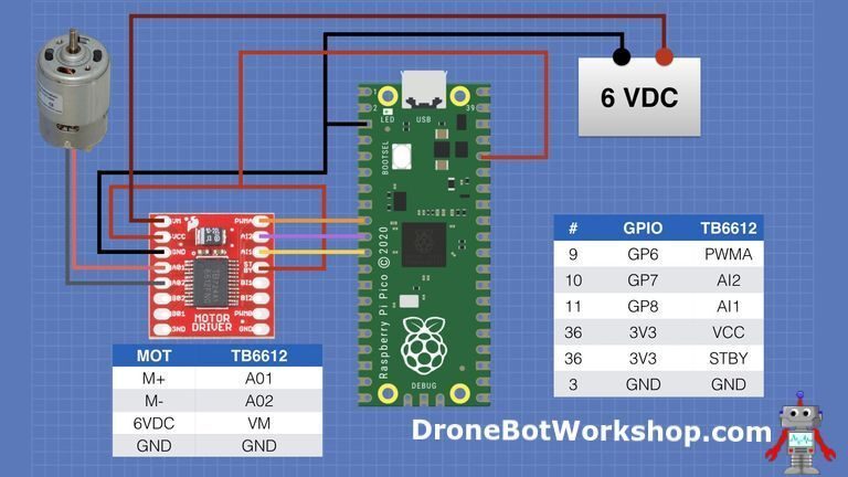
We will only use one motor for this demonstration. We will use the TB6612FNG H-Bridge and the Raspberry Pi Pico to control a small DC motor.
TB6612FNG H-Bridge
The TB6612FNG H-Bridge is one we have used before, a MOSFET-based H-Bridge that has many performance advantages over the older L-298N alternative.
This device actually has two channels, but we will only deal with channel A for demonstration.
Channel A has three inputs.
-
AI1 – Direction and mode -
AI2 – Direction and mode -
PWMA – A PWM input to control motor speed.
Between them, the AI1 and AI2 pins control the motor direction and mode. Modes include short braking and stopping modes; in our simple demonstration, we will only deal with direction mode.
The TB6612FNG H-Bridge also has power and motor connections on the other side of the board.
Here is how we will connect the TB6612FNG H-Bridge to the Raspberry Pi Pico.

Please note that since I am using a 6V motor, I have provided a 6V power supply for it. Do not attempt to power your motor with the Pico’s output voltage; a separate power supply is necessary. I used four AA batteries, which is a simple and safe arrangement.
The polarity of the motor does not actually matter; it just determines which way is forward and which way is backward.
Once it is all connected, we need some code to run it. I suggest doing it like this.
# Raspberry Pi Pico Motor Test
# motor-test.py

# POT - Pico GPIO 26 ADC0 - Pin 32

# RED BUTTON - Pico GPIO 15 - Pin 20
# BLACK BUTTON - Pico GPIO 2 - Pin 4

# RED LED - Pico GPIO 10 - Pin 14
# GREEN LED - Pico GPIO 11 - Pin 15
# BLUE LED - Pico GPIO 14 - Pin 19

# DroneBot Workshop 2021
# https://dronebotworkshop.com

import machine
import utime

potentiometer = machine.ADC(26)

mtr_AI1 = machine.Pin(8, machine.Pin.OUT)
mtr_AI2 = machine.Pin(7, machine.Pin.OUT)
mtr_PWMa = machine.PWM(machine.Pin(6))

button_red = machine.Pin(15, machine.Pin.IN, machine.Pin.PULL_DOWN)
button_black = machine.Pin(2, machine.Pin.IN, machine.Pin.PULL_UP)

led_red = machine.Pin(10, machine.Pin.OUT)
led_green = machine.Pin(11, machine.Pin.OUT)
led_blue = machine.Pin(14, machine.Pin.OUT)

led_red.value(0)
led_green.value(0)
led_blue.value(1)

mtr_PWMa.freq(50)
mtr_AI1.value(1)
mtr_AI2.value(0)

while True:

    mtr_PWMa.duty_u16(potentiometer.read_u16())

    if button_red.value() == 1:
        mtr_AI1.value(0)
        mtr_AI2.value(1)
        led_red.value(1)
        led_green.value(0)
        led_blue.value(0)

    if button_black.value() == 0:
        mtr_AI1.value(1)
        mtr_AI2.value(0)
        led_red.value(0)
        led_green.value(1)
        led_blue.value(0)

    utime.sleep(0.25)
We are going to use the potentiometer, two switches, and the RGB LED, along with the motor controller. The potentiometer will control the speed of the motor, the switches will control the direction, and the LEDs will indicate the current direction with colored lights.
We use our previous two libraries and set up the potentiometer as before.
Next, we define the Pico’s connections to the TB6612FNG H-Bridge as outputs. The PWMA output on GPIO 6 is defined as PWM, which will control the motor speed.
The setup for the LEDs and buttons is the same as before.
The PWM frequency is set to 50Hz, which is an arbitrary choice. Feel free to experiment and see if it improves motor performance.
The motor’s AI1 and AI2 inputs are set to rotate in the forward direction, so the motor will start in the forward direction. Note that the blue segment of the RGB LED will also be turned on when we start.
In the True loop, we read the value from the potentiometer and pass it to the motor’s PWM signal to control the motor speed. We also check the state of the buttons.
If the red button is pressed, we set the AI1 and AI2 signals to reverse the motor. We also light up the red LED segment.
If the black button is pressed, we set the motor direction to forward and turn on the green LED segment.
Load and check the code. It should start with a blue LED, and you should be able to control the speed of the motor. Pressing the buttons will control the direction and change the color of the LEDs.
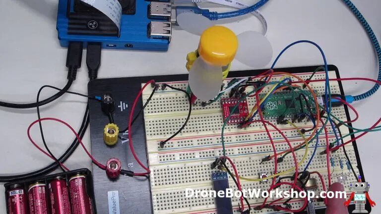
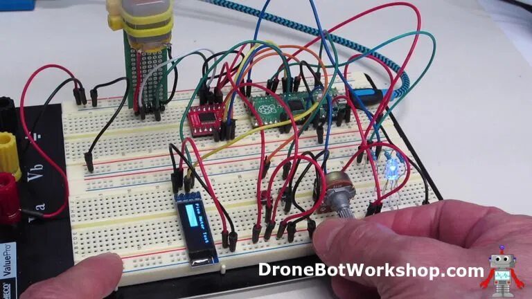
Pico Everything Demonstration
Finally, let’s put everything together for a big final demonstration. We are not far from doing this, as in the previous script we used everything except the OLED display.
So let’s add the OLED display to this combination. Here is the code we need to do.
# Raspberry Pi Everything Test
# everything.py

# POT - Pico GPIO 26 ADC0 - Pin 32

# RED BUTTON - Pico GPIO 15 - Pin 20
# BLACK BUTTON - Pico GPIO 2 - Pin 4

# RED LED - Pico GPIO 10 - Pin 14
# GREEN LED - Pico GPIO 11 - Pin 15
# BLUE LED - Pico GPIO 14 - Pin 19

# DroneBot Workshop 2021
# https://dronebotworkshop.com

import machine
import utime

potentiometer = machine.ADC(26)

mtr_AI1 = machine.Pin(8, machine.Pin.OUT)
mtr_AI2 = machine.Pin(7, machine.Pin.OUT)
mtr_PWMa = machine.PWM(machine.Pin(6))

button_red = machine.Pin(15, machine.Pin.IN, machine.Pin.PULL_DOWN)
button_black = machine.Pin(2, machine.Pin.IN, machine.Pin.PULL_UP)

led_red = machine.Pin(10, machine.Pin.OUT)
led_green = machine.Pin(11, machine.Pin.OUT)
led_blue = machine.Pin(14, machine.Pin.OUT)

sda=machine.Pin(20)
scl=machine.Pin(21)

i2c=machine.I2C(0, sda=sda, scl=scl, freq=400000)

from ssd1306 import SSD1306_I2C
oled = SSD1306_I2C(128, 32, i2c)

oled.text('Pico Motor Test', 0, 0)
oled.show()
utime.sleep(2)

led_red.value(1)
led_green.value(0)
led_blue.value(0)
utime.sleep(2)

led_red.value(0)
led_green.value(1)
led_blue.value(0)
utime.sleep(2)

led_red.value(0)
led_green.value(0)
led_blue.value(1)

mtr_PWMa.freq(50)
mtr_AI1.value(1)
mtr_AI2.value(0)

while True:

    speedvalue = int((potentiometer.read_u16())/500)

    mtr_PWMa.duty_u16(potentiometer.read_u16())

    if button_red.value() == 1:
        mtr_AI1.value(0)
        mtr_AI2.value(1)
        led_red.value(1)
        led_green.value(0)
        led_blue.value(0)

    if button_black.value() == 0:
        mtr_AI1.value(1)
        mtr_AI2.value(0)
        led_red.value(0)
        led_green.value(1)
        led_blue.value(0)

oled.fill_rect(1,15,speedvalue,25,1)
oled.show()
oled.fill_rect(1,15,speedvalue,25,0)
utime.sleep(0.25)
Now you should recognize most of this code; it is basically the previous script with the I2C OLED display library and setup added. Aside from that, the first few lines are the same, with a sequence of LED colors, and once everything is set up, there will be a display print.
In the True loop, we see that an integer called “speedvalue” is being calculated. This variable will be used to set the size of the bar graph displayed on the OLED.
The red and black buttons operate exactly the same as before.
Then, the OLED draws a rectangle under its title line and fills the rectangle. The length of the rectangle is determined by “speedvalue,” so as the speed increases, the rectangle will get longer.
In a sense, we are using the OLED as a rough speed indicator, or a speedometer!
Set everything up and watch the demonstration. It should operate the same as previous experiments, only this time we have a display showing the motor speed along with an RGB LED indicating its direction.
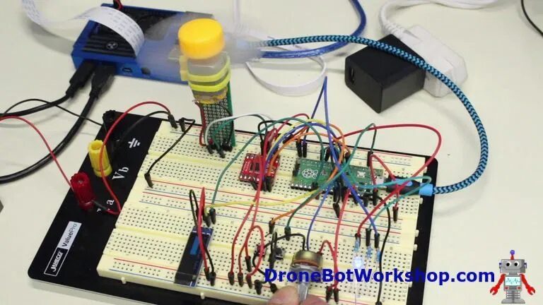
Running Without a Host
So far, everything we have done has been loading programs onto the Pico from the Thonny IDE to run.
However, once you have developed a program, you will want it to run independently, powered by the microUSB port or through the Pico’s VSYS power input.
Your program or programs are now stored on the Pico. So how do we make it run at startup?
The answer is that we change the name of the program!
Main Program main.py
When the Pico starts up, it looks for a program named main.py. If it finds it, it will load it and run it at startup.
Therefore, if you want your program to run unattended, you need to save it as main.py. Later, if you wish, you can rename main.py to another program or delete it altogether.
First, load the program you want to run at startup into Thonny IDE. Now click on “File” and select “Save As”.
You will be asked whether to save it on your local computer or on the Pico; you definitely want to save it on the Pico.
Now save your program as “main.py”. Just like that, all in lowercase.
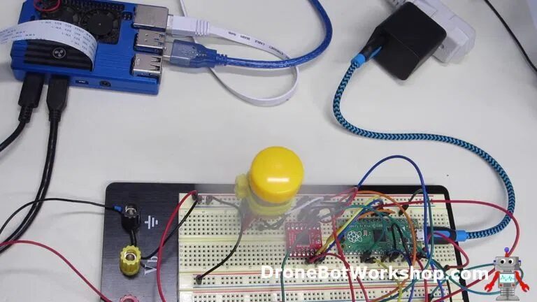
Now unplug the Pico from the computer and plug it into a suitable power source, such as a USB adapter. You will see the Pico reboot and run the program you saved as “main.py”.
Conclusion
This is clearly just the beginning of the Raspberry Pi Pico.
I hope to see PlatformIO and Arduino IDE support for the Raspberry Pi Pico, as the current method of creating C++ programs for the Pico is somewhat cumbersome, especially for beginners.
But it is a great and inexpensive entry into MicroPython, and you will see more things here.
So grab a Pico and start experimenting as soon as possible!
Resource Overview
-
Pico Code[1] – All MicroPython code used in this article, packaged in a convenient ZIP file.
-
Raspberry Pi Pico[2] – The official announcement page for the Raspberry Pi Pico.
-
Pico Pinout[3] – PDF document of the Raspberry Pi Pico pinout.
-
Pico Datasheet[4] – PDF document containing technical specifications and ratings for the Pico.
-
RP2040 Datasheet[5] – PDF document containing all specifications of the RP2040 microcontroller. Warning, this is a very large document.
-
Pico MicroPython SDK[6] – Good PDF guide for using MicroPython on the Raspberry Pi Pico.
-
Pico C++ SDK[7] – PDF guide for C++ on the Pico. This is also a very large document.
Translation first published in DF Maker Community: https://mc.dfrobot.com.cn/thread-308442-1-1.html
Original link: https://dronebotworkshop.com/pi-pico/
Reference Materials
Pico Code: http://dbot.ws/picocode
[2]Raspberry Pi Pico: https://www.raspberrypi.org/blog/raspberry-pi-silicon-pico-now-on-sale/
[3]Pico Pinout: https://datasheets.raspberrypi.org/pico/Pico-R3-A4-Pinout.pdf
[4]Pico Datasheet: https://datasheets.raspberrypi.org/pico/pico-datasheet.pdf
[5]RP2040 Datasheet: https://datasheets.raspberrypi.org/rp2040/rp2040-datasheet.pdf
[6]Pico MicroPython SDK: https://datasheets.raspberrypi.org/pico/raspberry-pi-pico-python-sdk.pdf
[7]Pico C++ SDK: https://datasheets.raspberrypi.org/pico/raspberry-pi-pico-c-sdk.pdf