Abstract
At present, developing a new type of paper-counting device without special requirements on paper size or material is of great importance to the paper industry and printing industry. When the parallel plate capacitor is used as the sensor to measure the number of paper, the capacitance of the capacitor will change with the number of paper. Taking into account of this size effect of the parallel plates, the laws of the capacitance of different size capacitors changing with the number of paper are found out by using the methods of theoretical calculation, finite element simulation and experimental verification. Finally, using the STM32F103C8T6 minimum system board as the control center, a paper-counting device is built by a parallel-plate capacitor, a FDC2214 capacitance sensor and a man-machine interactive system. After calibrating the device with standard A4 paper, the accuracy of paper counting in 60 sheets is up to 100%. The device can also be used to measure the number of other insulating paper or cloth, etc.
Keywords Parallel Plate Capacitor; Size Effect; Finite Element; STM32; Paper Measurement
1 Theory and Experimental Analysis of Paper Measurement Using Parallel Plate Capacitor
1.1 Size Effect of Parallel Plate Capacitor
The formula given in college physics textbooks for a parallel plate capacitor with plate area S and plate spacing d is
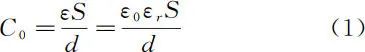
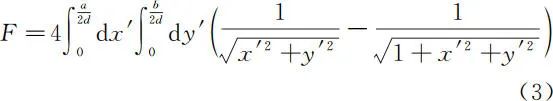
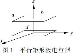
where ε0 is the permittivity of free space, with a value of 8.854×10⁻¹²F/m, and εr is the relative permittivity of the medium between the plates. This formula is derived under the assumption of ignoring the edge effects of the capacitor, considering the two plates as approximately infinite charged planes, and assuming a uniform electric field between the two plates. Literature [4] proposed the size effect of parallel plate capacitors and provided the laws of capacitance variation with size for parallel circular and rectangular plate capacitors. The paper measurement device uses rectangular parallel plate capacitors, with the lengths of the two rectangular plates being a and b, and the distance between the plates being d, adopting x, y, z coordinate systems. The lower plate is in the xy plane, the x axis is parallel to the length a of the lower plate, the y axis is parallel to the length b of the lower plate, the origin is at the center of the lower plate, the upper plate is in the z=d plane, and the z axis is the central axis of the two plates, with the relative permittivity of the medium between the two plates being εr. A schematic diagram of the parallel plate capacitor is shown in Figure 1. Assuming the charge on the two plates is uniformly distributed, the capacitance of the parallel rectangular plate capacitor is calculated as
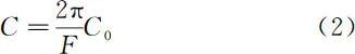
where F is a dimensionless integral
1.2 Theoretical and Experimental Methods for Analyzing Capacitance Variation
The paper measurement device measures standard A4 paper, with an average thickness of 0.104mm and a relative permittivity of 2.5. Four different sizes of rectangular electrode plates are selected with lengths a×b of 50mm × 50mm, 100mm × 150mm, 100mm × 200mm, and 150mm × 200mm. When the distance d between the two parallel plates increases with the number of papers from 1 to 100, the ideal capacitance values corresponding to the four different sizes of plates can be calculated using formulas (1) to (3) after considering the size effect of the plates.
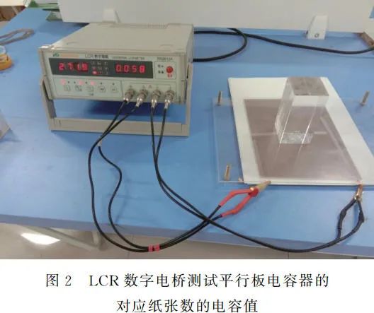
For experimental verification of the capacitance variation with paper, two single-sided copper-clad plates are used as the upper and lower electrodes of the capacitor, fixed on two non-conductive acrylic plates. The testing setup is shown in Figure 2. Standard A4 paper is placed in the middle of the plates, and the capacitance value is tested using an RS2812A LCR digital bridge. The simulation of capacitance variation with paper is performed using electromagnetic finite element simulation software Ansoft Maxwell3D[5], after establishing the model for the parallel plate capacitor paper measurement.
1.3 Comparison of Results for Capacitance Variation Analysis
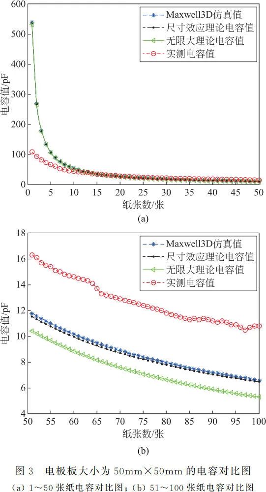
When the electrode plate size is 50mm×50mm, the comparison results of capacitance obtained by the above methods are shown in Figure 3. From Figure 3(a), it can be seen that with a smaller number of papers, the capacitance values calculated by the two theoretical methods and the capacitance values simulated by Ansoft Maxwell3D software match well. However, when the number of papers is less than 10, the capacitance value measured by the digital bridge is smaller than the capacitance values obtained by the other three methods. This is due to the unevenness of the surfaces of the two plates and the height of the solder joints of the plate leads, which causes the distance between the plates to be greater than the actual thickness of the paper. But after 10 sheets, the capacitance values obtained by the four different methods are very close. The trend of capacitance variation shows that as the number of papers increases, the distance between the two plates increases, and the trend of capacitance value decreasing becomes slower. From Figure 3(b), it can be seen that as the number of papers increases, the size effect of capacitance becomes more apparent, with the theoretical capacitance values considering the size effect matching well with the capacitance values simulated by Ansoft Maxwell3D software, both being larger than the ideal capacitance value. The capacitance value measured by the digital bridge is the largest because the increased weight of the paper compresses it, reducing the actual distance between the plates compared to the theoretical distance.
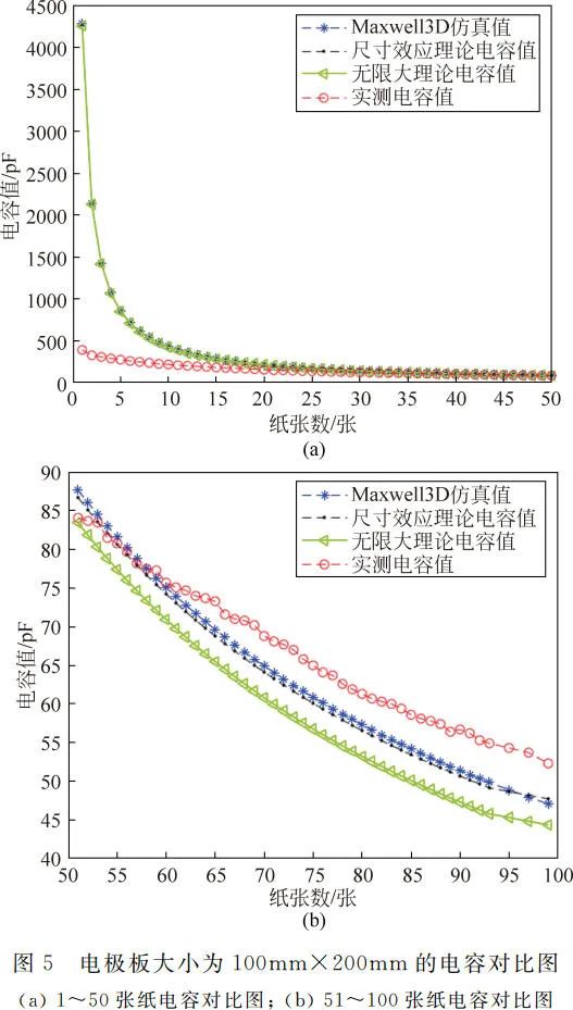
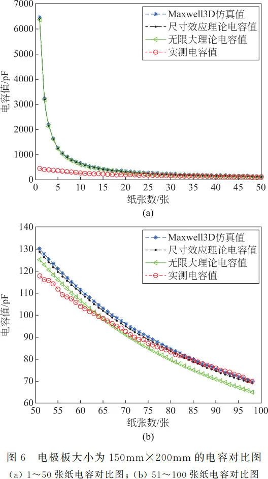
Comparison results of capacitance for electrode plate sizes of 100mm×150mm, 100mm×200mm, and 150mm×200mm are shown in Figures 4, 5, and 6 respectively. The overall trend of capacitance variation is similar to that in Figure 3, with the distance between the plates increasing as the number of papers increases, and the trend of capacitance value decreasing becoming slower. The measured capacitance values are smaller than those obtained by the other three methods when the number of papers is small, but as the number of papers increases, the measured capacitance values become larger than those obtained by the three methods. When fixing a certain calculation or experimental method, comparing Figures 3, 4, 5, and 6 reveals that as the size of the electrode plates increases, the capacitance values corresponding to the same number of papers increase, indicating that with a fixed plate distance, capacitance values increase with the area of the plates.
2 Overall Design of the Paper Measurement Device
2.1 Hardware Design and Working Principle of the Paper Measurement Device
The hardware part of the paper measurement device consists of a power module, STM32F103C8T6 microcontroller minimum system board, human-machine interaction module (OLED display module, voice broadcast module, and key input module), FDC2214 capacitance sensor device, and parallel plate capacitor. The hardware block diagram of the paper measurement device is shown in Figure 7. The STM32F103 series is a 32-bit ARM microcontroller based on the ARM Cortex-M3 core[6,7], with a program memory capacity of 64KB and a maximum speed of 72MHz. The FDC2214 capacitance sensor is a low-power, high-precision capacitance sensor chip from TI, with a resonance frequency ranging from 10kHz to 10MHz, a data bit of 28 bits, which means a precision of 1/228, and the FDC2214 has 4 acquisition channels, communicating with the MCU via IIC[8,9].
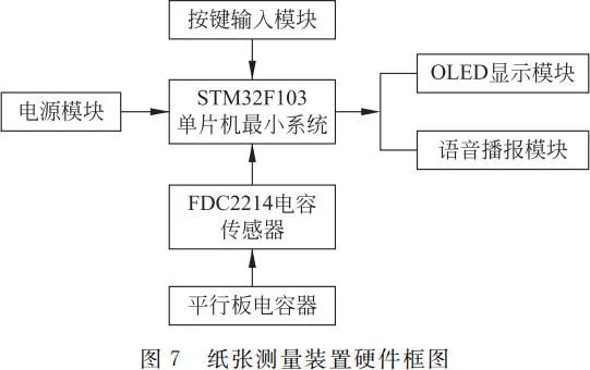
The working principle of the paper measurement device is that the STM32F103C8T6 microcontroller minimum system board detects the change in capacitance value of the parallel plate capacitor through the FDC2214 capacitance sensor to identify the corresponding number of papers, and displays the paper count n on the OLED display module.
The FDC2214 capacitance sensor detects capacitance based on the principle of RLC parallel resonance. There are four detection channels at the front end of this chip, but we only use one detection channel. The capacitance to be measured Cx is connected to this sensor, making it part of the oscillation circuit, parallel to the capacitance element C and inductance L, as shown in Figure 8. The sensor generates a resonance frequency
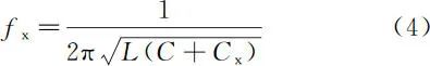
When the physical quantity of the number of papers n changes, causing the capacitance Cx to change, the resonance frequency fx generated by the internal oscillator of the FDC2214 chip also changes, and the sensor outputs a digital value DATAX to the STM32F103C8T6 microcontroller by comparing the resonance frequency fx with the internal reference clock frequency fref.

The digital value DATAX is proportional to the resonance frequency fx and corresponds to the measured capacitance Cx. In this design, the capacitance value of the oscillating circuit C is set to 33pF, and the inductance L is set to 18μH, with the internal reference clock frequency fref being 40MHz.
2.2 Software Design of the Paper Measurement Device
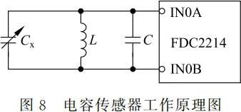
The paper measurement device has two modes: calibration and measurement. The calibration mode is for learning to read different numbers of papers, and the calibration results are stored in the microcontroller. After calibration, it can switch to measurement mode through key operation. In measurement mode, the number of papers can be identified based on the paper measurement characteristic curve using a piecewise linear interpolation algorithm, and the number of measured papers n and the corresponding digital value DATAX are displayed on the OLED display module. The software flow framework of the system is shown in Figure 9.
3 Measurement and Result Analysis of the Paper Measurement Device
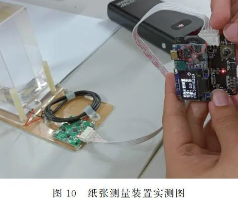
The actual measurement setup of the paper measurement device is shown in Figure 10.
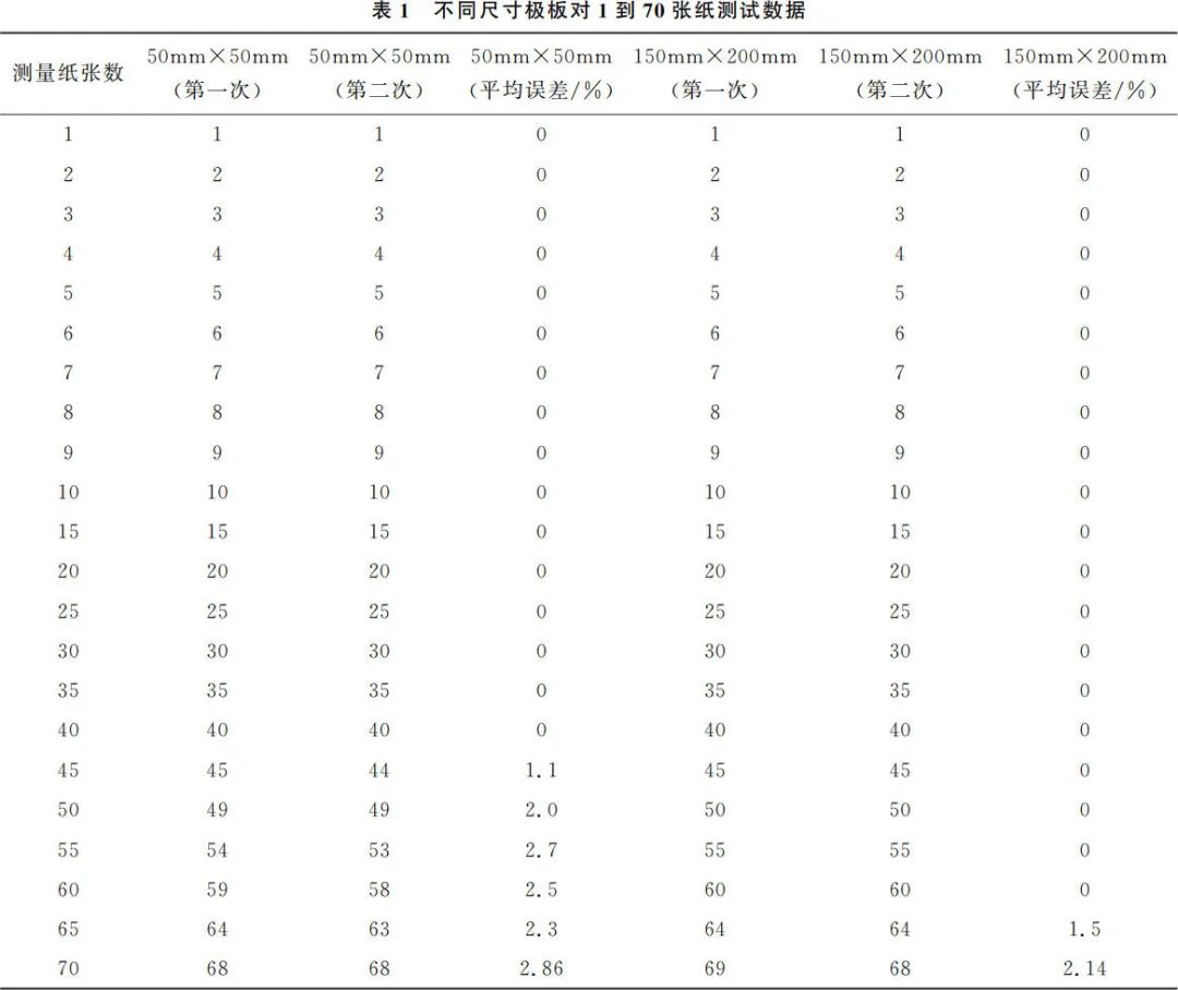
When the sizes of the parallel plate capacitor plates are 50×50mm and 150×200mm, the test results are shown in Table 1. When the plate size is 50mm×50mm, the testing device is very accurate for up to 40 sheets of paper after calibrating with 70 sheets, but the testing error gradually increases after exceeding 40 sheets. When the plate size is 150mm×200mm and the testing device is calibrated with 70 sheets, the testing results are accurate for up to 60 sheets, but the testing error gradually increases after exceeding 60 sheets. It can be seen that under the same testing conditions, considering the size effect of the parallel plate capacitor, using a relatively larger plate size of 150mm×200mm results in a larger capacitance value for the same number of papers, providing better distinguishability and more accurate testing results.
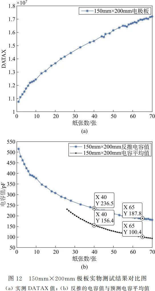
When the plate size is 50mm×50mm, the output number of papers n corresponding to the resonance frequency digital value DATAX is shown in Figure 11(a). The corresponding capacitance values are derived using equations (4) and (5), indicated by star-shaped data points in Figure 11(b), such as the capacitance value for 20 sheets being 104.1pF and for 40 sheets being 89.36pF. The average capacitance values corresponding to the number of sheets n obtained by various analytical methods are calculated, with the average capacitance for 20 sheets being 27.9pF and for 40 sheets being 15.4pF. Excluding the first 10 sheets with larger errors, the average capacitance values for 11 to 49 sheets are plotted in black solid points in Figure 11(b). It is found that the derived capacitance values are larger than the average capacitance values obtained in Figure 3, with the capacitance difference for 20 sheets being 76.2pF and for 40 sheets being 73.96pF. The average capacitance difference for 11 to 49 sheets is calculated to be 75.3pF, which is the capacitance introduced by the measurement leads of the detection device. The capacitance introduced by the measurement leads is in parallel with the capacitance of the parallel plates, hence the derived capacitance values are the sum of the capacitance of the parallel plates and the capacitance introduced by the measurement leads. Figure 12(a) shows the digital value DATAX corresponding to the resonance frequency for a plate size of 150mm×200mm, with the derived capacitance values indicated by star-shaped data points in Figure 12(b). Excluding the first 25 sheets with larger errors, the average capacitance values obtained by various analytical methods for 26 to 70 sheets are plotted in black solid points in Figure 12(b). The final calculated difference between the derived capacitance values and the average capacitance values obtained in Figure 6 is averaged to be 81.07pF. Therefore, the measurement lead capacitance introduced by this measurement device is approximately 78.2pF.

4 Conclusion
After considering the size effect of the parallel plate capacitor, the capacitance variation laws with paper are analyzed using different methods, employing the STM32F103C8T6 minimum system board as the control center, along with a parallel plate capacitor, FDC2214 capacitance sensor, and human-machine interaction system to construct a paper measurement device. The accuracy of measurement for 50mm×50mm plates is 100% for up to 40 sheets, with measurement error gradually increasing as the number of papers increases. The accuracy of measurement for 150mm×200mm plates is 100% for up to 60 sheets, with measurement error also gradually increasing thereafter. This device can also be used for quantity detection of other insulating papers or fabrics.
References
[1] Zhu Haibin. Research and Development of Machine Vision Detection Device for Layered Quantity of Cigarette Labels[D]. Changsha: Hunan University, 2013.
[2] Yang Dongxing, Liu Chunxia. Design of Paper Identification Device Based on FDC2214 Piecewise Linear Regression[J]. Technology Innovation and Application, 2020(31): 84-86.
[3] Zhai Wensheng, Shao Mingjie, Wang Tianyu. Design of Paper Measurement System Based on FDC2214[J]. Internet of Things Technologies, 2020, 10(5): 73-76, 79.
[4] Cao Xiaoge, Yang Yang. The Size Effect of Parallel-Plate Capacitor[J]. College Physics, 2021, 40(3): 8-11.
[5] Zhao Bo, Zhang Hongliang. Application of Ansoft 12 in Engineering Electromagnetics[M]. Beijing: China Water Power Press, 2015.
[6] Han Ren, Jin Yongwei, Wang Qiang. Design of Car Reversing Radar Warning System Based on STM32 and Ultrasonic Ranging[J]. Transducer and Microsystem Technologies, 2016, 35(4): 63-66.
[7] Xie Meng, Guo Xia. Design of Control System for Smart Car[J]. Transducer and Microsystem Technologies, 2016, 35(12): 110-112.
[8] Guo Xia, Tan Yali, Shen Miao. Gesture Recognition System Based on FDC2214[J]. Transducer and Microsystem Technologies, 2018, 37(12): 90-92.
[9] Wu Shaoyi, Zhang Fuchun, Yang Yanning, et al. Design of Gesture Password Lock Based on FDC2214[J]. Electronic Design Engineering, 2019, 27(21): 93-96, 101.
Funding Project: Shaanxi Provincial Education Science “13th Five-Year Plan” 2020 Annual Project (SGH20Y1380).
Author Profile: Cao Xiaoge, female, lecturer at Xi’an Jiaotong University City College, mainly engaged in teaching and research in electromagnetic fields, [email protected].
Citation Format: Cao Xiaoge, Zhang Yanxiao, Wu Jiale, et al. Paper-counting device based on parallel-plate capacitor under size effect[J]. Physics and Engineering, 2022, 32(4): 203-209.
Cite this article: CAO X G, ZHANG Y X, WU J L, et al. Paper-counting device based on parallel-plate capacitor under size effect[J]. Physics and Engineering, 2022, 32(4): 203-209. (in Chinese)