As we all know, although LTE and NB-IoT are closely related, the design goal of LTE is high speed and large data volume, while NB-IoT is designed for the “intermittent transmission of small data” for the Internet of Things (IoT), making their directions opposite. Therefore, the LTE core network (EPS) is no longer suitable for NB-IoT applications and needs to be optimized.

To improve the transmission efficiency of small data in the NB-IoT system, the 3GPP SA2 working group began researching the CIoT EPS optimization architecture in July 2015, proposing that CIoT EPS needs to support four major functions:
① Support for ultra-low power IoT terminals
② Support for a large number of IoT devices connected per cell
③ Support for narrowband spectrum wireless access technology
④ Support for enhanced coverage for IoT
And simplify the functions, cutting four functions from LTE EPS:
① No emergency call service provided
② Does not support traffic offloading, such as local IP access (LIPA) and selective IP traffic offloading
③ In EPS connection management, only re-selection in IDLE mode is supported, and handover in CONNECTED mode is not supported
④ GBR bearer and dedicated bearer establishment are not supported
Finally, 3GPP proposed two optimization schemes: Control Plane Optimization Transmission Scheme (C-Plane CIoT EPS optimization) and User Plane Optimization Transmission Scheme (U-Plane CIoT EPS optimization). For IoT terminals, “Control Plane Optimization Transmission Scheme” must be supported, and “User Plane Optimization Transmission Scheme” may be optionally supported.
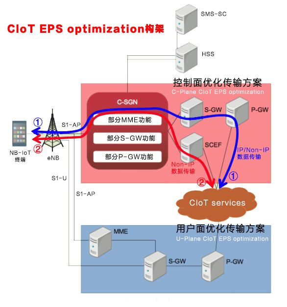
Control Plane Optimization Transmission Scheme
The Control Plane Optimization Transmission Scheme allows small data packets to be transmitted over the control plane, with data encapsulated in the format of Non-Access Stratum Protocol Data Units (NAS PDUs) within control plane signaling messages for transmission. This concept is similar to shopping in a mall; if a consumer only purchases a small number of items, they can check out via a designated fast lane.
This scheme reduces the control plane signaling overhead when transmitting data, thereby helping to lower terminal power consumption and reduce bandwidth usage.
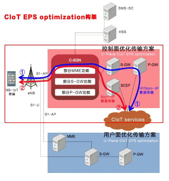
As shown in the figure, the Control Plane Optimization Transmission Scheme supports both IP data and Non-IP data transmission, with two transmission paths: ① Transmitting through S-GW to P-GW and then to the application server (CIoT Services); ② Connecting to the application server via SCEF (Service Capability Exposure Function), which only supports Non-IP data transmission.
Based on the transmission path and whether IP data transmission is supported, there are three transmission modes:
Transmission Path ① (IP Data Transmission)
The transmission path is from S-GW to P-GW and then to the application server, allowing for the rapid deployment of NB-IoT using existing IP communication technologies. However, the downside is low security, and without passing through SCEF, telecom operators remain as mere pipelines.
Transmission Path ① (Non-IP Data Transmission)
The transmission path is still from S-GW to P-GW and then to the application server, but since there are no IP address data packets being transmitted, there must be a mapping between the NB-IoT terminal’s ID and the AS’s IP address + port number at P-GW to correctly transmit the data packets at the SGi interface. This method is referred to as Point-to-Point (PtP) Tunneling technology for UDP/IP. The parameters of the tunnel, specifically the destination IP address and UDP port number, must be pre-configured at P-GW, making P-GW a transparent transmission node for the data transmitted between the NB-IoT terminal and AS.
This method has high security and is power-efficient, but it requires the development of new point-to-point tunneling technology.
Transmission Path ② (Non-IP Data Transmission)
This path transmits Non-IP data via SCEF, which only supports Non-IP data transmission and is a Non-IP exclusive solution. This method has many advantages, including high security, energy efficiency, and the ability for operators to create new business value, but it requires the establishment of new SCEF network element nodes and the development of new API technologies.
SCEF
SCEF is a new node added for NB-IoT, which provides services to AS through API interfaces rather than directly sending data, allowing telecom operators to not just be pipelines but to securely open their business capabilities to third-party service providers, enabling big data analysis of the IoT to create new business value.
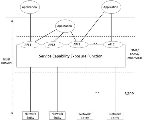
The SCEF architecture is shown in the figure above. For security reasons, SCEF is placed in a trusted domain of the operator (Trust Domain) and connects to services through APIs from OMA (Open Mobile Alliance), GSMA (Groupe Speciale Mobile Association), or other standard organizations (Standardisation Bodies, SDOs). Additionally, SCEF’s APIs support various types, such as DIAMETER, RESTful APIs, and XML over HTTP, allowing SCEF to be flexibly applied in different networks. Network Entity refers to nodes related to HSS, MME, P-GW, PCRF, or billing and security.
C-SGN
C-SGN, or CIoT Serving Gateway Node, is a new node introduced in the Control Plane Optimization Transmission Scheme, created by merging the minimum functionalities of the control plane node MME and user plane nodes S-GW and P-GW into a single logical entity. The C-SGN functionality can also be deployed in the existing EPS’s MME.
HLCom
In the Control Plane Optimization Transmission Scheme, the HLCom mechanism, or Optimization to support High Latency Communication, is introduced, which caches downlink data at S-GW. Since NB-IoT terminals intermittently receive data through technologies like PSM and eDRX to save power, when the NB-IoT terminal is in sleep mode, S-GW caches the downlink data and only sends this cached data to the terminal after it is awakened.
User Plane Optimization Transmission Scheme
The data transmission method uses user plane bearers like LTE EPS, but this optimization scheme introduces two new states, Suspend and Resume, at the RRC layer to adapt to the intermittent transmission characteristics of IoT data. It also requires NB-IoT terminals, eNB, and MME to store connection information to quickly restore connections, simplify signaling processes, and improve transmission efficiency.

After such optimization, bearers can be established on demand, thereby reducing terminal power consumption and supporting large-scale IoT device connections in a single cell. This scheme not only supports existing EPS functions but also allows for the transmission of Non-IP data via P-GW.
RRC Suspend Process
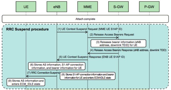
As shown in the figure, this process is activated by eNB, releasing the RRC connection between the NB-IoT terminal and eNB, as well as the S1-U bearer between eNB and S-GW.
Steps (1) and (2):
eNB sends a UE Context Suspend Request and initiates the release of the bearer information related to the NB-IoT terminal through MME to S-GW.
Step (3):
S-GW releases the S1-U bearer related to the NB-IoT terminal. Specifically, S-GW only releases the eNB address and the downlink tunnel endpoint identifier (TEID), while continuing to store other information.
Steps (4) and (5):
After completing the S1-U bearer release at S-GW, eNB receives the UE Context Suspend Response notification through MME.
Steps (6) and (7):
eNB stores the Access Stratum (AS) information, S1-AP connection information, and bearer information of the NB-IoT terminal, then sends the RRC Connection Suspend message to the NB-IoT terminal.
Step (8):
MME stores the S1-AP connection information and bearer information for the NB-IoT terminal and enters IDLE state.
Step (9):
Upon receiving the RRC Connection Suspend message from eNB, the NB-IoT terminal stores the AS information and enters IDLE state.
RRC Resume Process
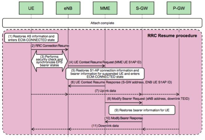
As shown in the figure, this process re-establishes (resumes) the RRC connection between the suspended NB-IoT UE and eNB, as well as the released S1-U bearer between eNB and S-GW. The Resume process is initiated and activated by the NB-IoT terminal.
Steps (1) and (2):
First, the AS information stored during the RRC Suspend process is used to restore the connection with the network.
Step (3):
At this time, eNB performs a security check on the NB-IoT terminal and provides the NB-IoT terminal with a list of restored radio bearers, synchronizing the EPS bearer state between the NB-IoT UE and eNB.
Step (4):
eNB sends a UE Context Resume Request to MME to notify that the connection with the NB-IoT terminal has been securely restored.
Steps (5) and (6):
After receiving the recovery notification from eNB, MME restores the S1-AP connection information and bearer information for the NB-IoT terminal, enters CONNECTED state, and sends a UE Context Resume Response message to eNB (including S-GW address and S1-AP connection information).
Step (7):
The NB-IoT terminal can now send uplink data to S-GW.
Steps (8) and (9):
MME sends the eNB address and downlink TEID to S-GW via Modify Bearer Request message to re-establish the downlink S1-U bearer between the NB-IoT terminal and S-GW.
Steps (10) and (11):
S-GW sends a Modify Bearer Response message to MME, then starts transmitting downlink data.
It is worth mentioning that when S-GW receives downlink data while the NB-IoT terminal is in Suspend state, S-GW will cache the data packets. Meanwhile, the Downlink Data Notification process is initialized between S-GW and MME, and then MME pages the NB-IoT terminal, thus activating the connection Resume process through the NB-IoT terminal.
Network Optimization Contributions Email: [email protected]
Long press the QR code to follow

On the communication road, let’s walk together!