Follow+Star Public Account, don’t miss exciting content
Source | PiZi Heng Embedded
Today, I will introduce the differences between normal GPIO and high-speed GPIO on i.MXRT.
1. What is HSGPIO?
HSGPIO is the abbreviation for High-Speed GPIO, sometimes also called tightly coupled GPIO or single-clock-cycle GPIO. In simple terms, its module (IP) clock source speed is higher than that of the normal GPIO clock source, allowing us to access its module registers at a higher frequency. The table below lists the distribution of HSGPIO across various i.MXRT models:
| Model | Normal GPIO | High-Speed GPIO |
|---|---|---|
| i.MXRT1010 | GPIO1, GPIO5 | GPIO2 |
| i.MXRT1060/1064 | GPIO1 – GPIO5 | GPIO6 – GPIO9 |
| i.MXRT1160/1170 | GPIO1 – GPIO13 | CM7_GPIO2, CM7_GPIO3 |
Taking the i.MXRT1060 as an example, if we look at its reference manual in the CCM clock module section, we can see that the clock source for normal GPIO1-5 is IPG_CLK_ROOT, while the clock source for high-speed GPIO6-9 is AHB_CLK_ROOT:
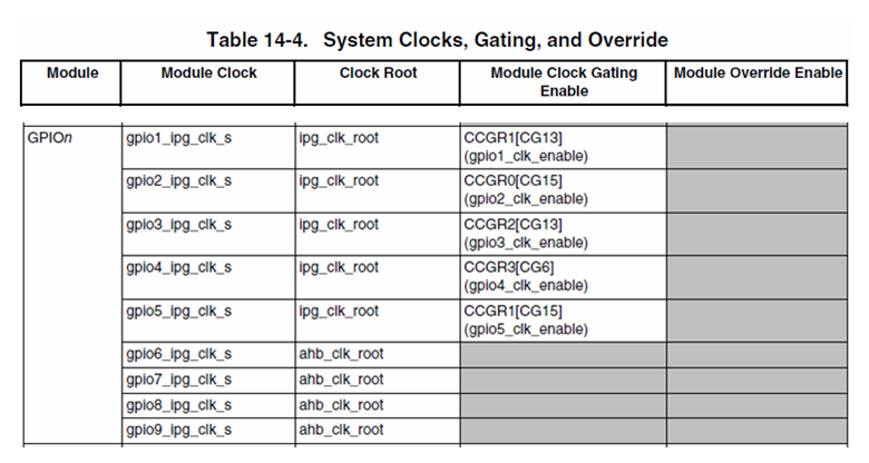
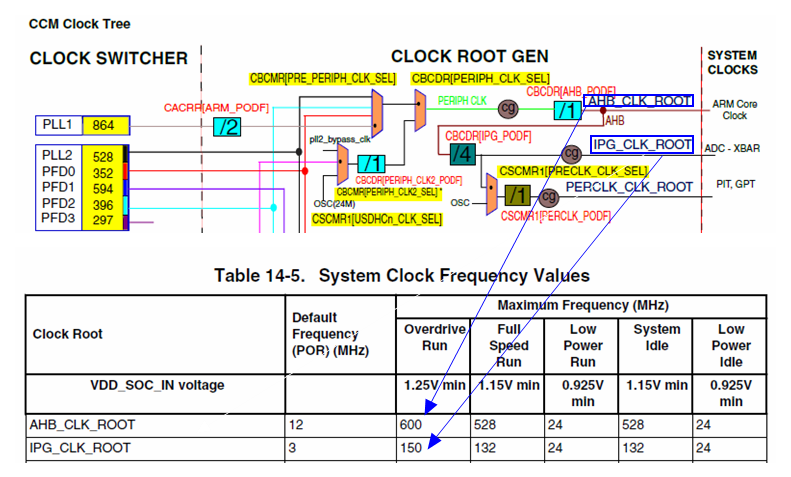
On the i.MXRT1060, the maximum frequency of IPG_CLK_ROOT is 150MHz, while AHB_CLK_ROOT, which is the core frequency, can reach 600MHz. Therefore, from the perspective of clock sources alone, the access performance of HSGPIO should be four times that of GPIO:
2. Shared PAD Design
Internally, the GPIO and HSGPIO modules are independent. However, due to limited external pin (PAD) resources, some HSGPIO share PAD with the GPIO module, which ultimately limits the actual I/O performance to the characteristics of the same physical PAD.
Taking the simplest packaged i.MXRT1010 as an example, the leftmost part of the figure lists all the PADs, where GPIO_SD[13:0] is dedicated to HSGPIO, while GPIO[13:0] and GPIO_AD[14:0] are shared pins for GPIO and HSGPIO. When these GPIO/HSGPIO shared pins are configured for GPIO functionality, they can map to GPIO1 (normal GPIO) or GPIO2 (HSGPIO):
Note: If GPIO_SD[13:0] has been configured for GPIO2, do not configure GPIO[13:0] as HSGPIO, as conflicts will occur.

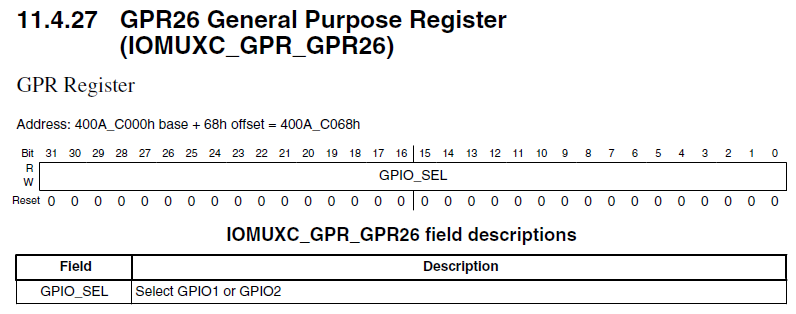
The specific GPIO mapping function is controlled by the IOMUXC_GPR26 register (note that this is a software reset and not a set register). For example, when GPIO_11 is configured for GPIOMUX_IO11 functionality, then IOMUXC_GPR26[11] determines its mapping relationship:
IOMUXC_GPR26[11] = 0, then GPIO_11 corresponds to GPIO1[11], as normal GPIO
IOMUXC_GPR26[11] = 1, then GPIO_11 corresponds to GPIO2[11], as HSGPIO
The table below lists the GPIO/HSGPIO switching control relationships for various i.MXRT models:
| Model | PAD Switching Control Register | ALT Function Name | Corresponding Switching GPIO |
|---|---|---|---|
| i.MXRT1010 | IOMUXC_GPR->GPR26 | GPIO_MUX | GPIO1 and GPIO2 |
| i.MXRT1060/1064 | IOMUXC_GPR->GPR26 IOMUXC_GPR->GPR27 IOMUXC_GPR->GPR28 IOMUXC_GPR->GPR29 |
GPIO_MUX1 GPIO_MUX2 GPIO_MUX3 GPIO_MUX4 |
GPIO1 and GPIO6 GPIO2 and GPIO7 GPIO3 and GPIO8 GPIO4 and GPIO9 |
| i.MXRT1160/1170 | IOMUXC_GPR->GPR40, 41 IOMUXC_GPR->GPR42, 43 |
GPIO_MUX2 GPIO_MUX3 |
GPIO2 and CM7_GPIO2 GPIO3 and CM7_GPIO3 |
3. PAD Operating Speed
As mentioned earlier, whether normal GPIO or HSGPIO is enabled, the final output signal is from the same physical PAD. Therefore, the actual I/O performance is ultimately limited by the maximum operating speed of this PAD.
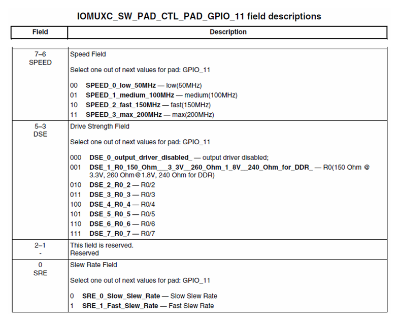
Continuing with the i.MXRT1010 as an example, each PAD in the IOMUXC module has a dedicated register IOMUXC_SW_PAD_CTL_PAD_xxIO for configuring electrical properties. For example, by selecting the corresponding configuration register for GPIO_11, the combination of the SRE, DSE, and SPEED bits can yield different operating speeds (specific combination values can be found in the reference manual in the GPIO section under Operating Frequency). However, we can see that the maximum operating speed of the PAD is 200MHz:
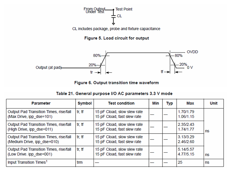
In the i.MXRT1010 data sheet, we can also see more specific I/O toggle time tests:
4. HSGPIO Example Code
Based on the theoretical knowledge above, we will modify the \\driver_examples\\gpio\\led_output example in the i.MXRT1010 SDK to add the following HSGPIO-related code, which can also achieve the function of blinking the LED light.
After discussing so much, if it is just using HSGPIO to control a small light to blink, it seems that the performance difference is not obvious. In the next article, the author will use an oscilloscope to measure the extreme toggle frequency of GPIO and HSGPIO. To give a sneak peek, the I/O toggle efficiency of GPIO->DR_TOGGLE and GPIO->DR registers is also different.
bool is_normal_gpio = false;

int main(void)
{
    BOARD_ConfigMPU();
    BOARD_InitBootClocks();

    /* Define the init structure for the output LED pin*/
    gpio_pin_config_t led_config = {kGPIO_DigitalOutput, 0, kGPIO_NoIntmode};

    CLOCK_EnableClock(kCLOCK_Iomuxc);
    IOMUXC_SetPinMux(IOMUXC_GPIO_11_GPIOMUX_IO11, 0U);
    if (is_normal_gpio)
    {
        // GPIO1
        IOMUXC_GPR->GPR26 &= ~(1u << 11);
        // Slow Slew Rate, 100MHz
        IOMUXC_SetPinConfig(IOMUXC_GPIO_11_GPIOMUX_IO11, 0x70A0U);
        GPIO_PinInit(GPIO1, 11, &led_config);
    }
    else
    {
        // GPIO2
        IOMUXC_GPR->GPR26 |= (1u << 11);
        // Fast Slew Rate, 200MHz
        IOMUXC_SetPinConfig(IOMUXC_GPIO_11_GPIOMUX_IO11, 0x70F9U);
        GPIO_PinInit(GPIO2, 11, &led_config);
    }

    while (1)
    {
        SDK_DelayAtLeastUs(100000, SDK_DEVICE_MAXIMUM_CPU_CLOCK_FREQUENCY);

        if (is_normal_gpio)
        {
            //GPIO1->DR_TOGGLE = (1u << 11);
            GPIO1->DR ^= (1u << 11);
            __DSB();
        }
        else
        {
            //GPIO2->DR_TOGGLE = (1u << 11);
            GPIO2->DR ^= (1u << 11);
            __DSB();
        }
    }
}
Thus, the differences between normal GPIO and high-speed GPIO on the i.MXRT have been introduced.
Click “Read the Original” for more sharing.