
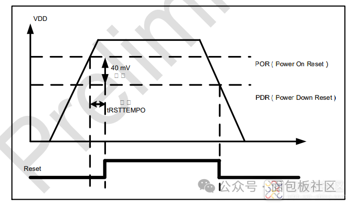
 PVD Programmable Voltage Detector The PVD (Programmable Voltage Detector) can be used to monitor the chip’s supply voltage and generate an interrupt when the supply voltage drops below a given threshold, allowing software to perform emergency handling. An interrupt is also generated when the supply voltage recovers above the given threshold, allowing software to handle power restoration. Power Consumption Control Modes If the goal of reducing chip current consumption is not achieved, various low-power modes provided by the MCU can be utilized to save power. The chip has six low-power modes. Low Power Run Mode: The CORE domain operates in low power mode, with memory and peripherals also operating in low power. Sleep Mode: The CORE domain operates in normal power mode while the CPU enters sleep mode, and memory and peripherals operate in normal power mode. Low Power Sleep Mode: The CORE domain operates in low power sleep mode, with the CPU entering low power sleep mode, while memory and peripherals operate in low power. Stop Mode: The CORE domain operates in low power mode, only retaining the contents of registers and RAM. Deep Stop Mode: The CORE domain operates in an even lower power mode, only retaining the contents of registers and RAM. Standby Mode: The CORE domain stops receiving power. All registers and SRAM contents are lost except for the backup circuit and backup domain. Deep Stop Mode Experiment The MCU is powered by VDD_M. We can remove the shorting cap and connect the power supply to measure MCU power consumption.
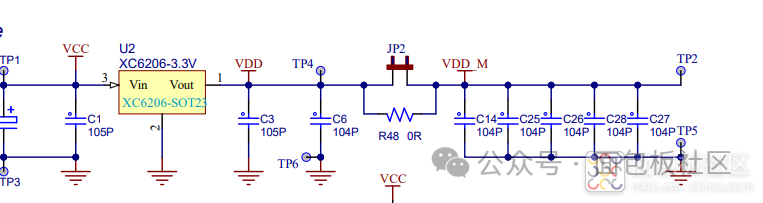 Code Analysis The code first blinks an LED 20 times, then uses
PWR_Pretreatment();RCC_APB1PeriphClockCmd(RCC_APB1Periph_PWRDBG, ENABLE);PWR_EnterSTOPMode(PWR_Regulator_LowPower, PWR_STOPEntry_WFI);PWR_Reinitialize();/*********************************************************************************************************************** * @brief * @note none * @param none * @retval none *********************************************************************************************************************/void PWR_DeepStop_EXTI_Wakeup_Sample(void){ uint8_t i = 0; printf("\r\nTest %s", __FUNCTION__); while (1) { printf("\r\n-->Running..."); for (i = 0; i < 20; i++) { PLATFORM_LED_Toggle(LED1); PLATFORM_DelayMS(100); } PWR_Pretreatment(); /* Deep Stop Mode */ RCC_APB1PeriphClockCmd(RCC_APB1Periph_PWRDBG, ENABLE); PWR_EnterSTOPMode(PWR_Regulator_LowPower, PWR_STOPEntry_WFI); PWR_Reinitialize(); }}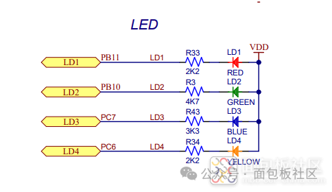
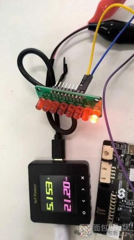 The MCU power supply is around 5.1V, and the power consumption when the LED is lit is about 20mA.
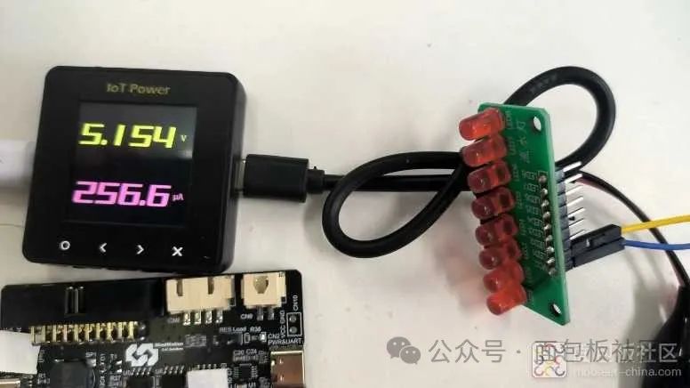 The MCU enters low power mode at 256 microamps.
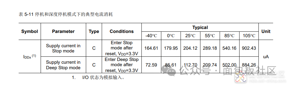 The manual states that Deep Stop is at 112.7 microamps, which is reasonable since I am providing power greater than 5V. Now Lingdong has improved a lot compared to two years ago.
END

 Click to read the original text, apply for the development board for free!