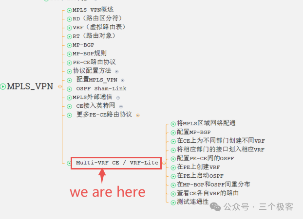
20th Article:Multi-VRF CE / VRF-Lite
In the previous section, we learned about more PE-CE routing protocols. In this section, we will start learning about Multi-VRF CE / VRF-Lite. Let’s dive in.
Multi-VRF CE / VRF-Lite
Overview
When the interface connecting the CE is placed in the VRF table on the PE, all CE data coming from this interface belongs to that VRF, and forwarding decisions are made based on that VRF. Therefore, user data coming from the same interface executes the same routing query. If a large company has two branches connected via the Internet, and each branch has multiple departments, then during normal MPLS_VPN implementation, either all departments of both companies can communicate because they share the same VRF routing table, or none can communicate.
Sometimes, due to business requirements, if we need to prevent communication between different departments of the two branches, according to MPLS_VPN theory, we should create separate VRFs for the departments that need to communicate and separate VRFs for those that do not, only then can we isolate the data of different departments.
Since all data from the CE connected to the PE interface belongs to the same VRF, it is impossible to create multiple VRFs when there is only one link between CE and PE. However, if the link between PE and CE is Ethernet, it can support sub-interface division, that is, different VLANs can be implemented through sub-interface division. Besides sub-interfaces, the best approach is to pull multiple lines between PE and CE.
If we only place different links into different VRFs on the PE, we can also meet the department isolation requirement. However, another method is to directly place interfaces connecting different departments into different VRFs on the CE. Normally, placing interfaces into VRFs is done on the PE, and the CE does not understand VRFs, meaning MPLS_VPN is transparent to the CE side. Now, to allow the CE to recognize VRFs and successfully assign different VRFs to different interfaces, we need to extend the CE to have PE functionality. This functionality is called Multi-VRF CE or VRF-Lite. While assigning VRFs to different interfaces on the CE, the VRFs on the PE will remain unremovable, so the PE functionality will not change. When the CE passes routing to the PE, the protocol running in between is OSPF, and the OSPF vrf-lite function also needs to be extended.
Below is an example illustrated to explain the configuration of VRF-Lite in detail.
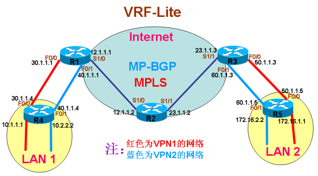
Note:The red part of the network is the departments that need to communicate but are isolated from the blue network departments. R1, R2, and R3 have been configured with loopback0, with addresses 1.1.1.1/32, 2.2.2.2/32, and 3.3.3.3/32 respectively, and OSPF has been configured to allow connectivity between all directly connected interfaces and loopback interfaces within the MPLS area. Below, we will take the configuration of the red network department communication as an example. The communication of the blue network department is similar to that of the red department; please refer to the configuration yourself.
1.ConfigureMPLS Area Network
Note:This step is skipped; please refer to the previous section for detailed steps.
2.ConfigureMP-BGP
Note:Configure MP-BGP between R1 and R3
(1) Configure MP-BGP on R1:
r1(config)#router bgp 100
r1(config-router)#neighbor 3.3.3.3 remote-as 100
r1(config-router)#neighbor 3.3.3.3 update-source loopback 0
r1(config-router)#address-family vpnv4
r1(config-router-af)#neighbor 3.3.3.3 activate
r1(config-router-af)#neighbor 3.3.3.3 send-community both
(2) Configure MP-BGP on R3:
r3(config)#router bgp 100
r3(config-router)#neighbor 1.1.1.1 remote-as 100
r3(config-router)#neighbor 1.1.1.1 update-source loopback 0
r3(config-router)#address-family vpnv4
r3(config-router-af)#neighbor 1.1.1.1 activate
r3(config-router-af)#neighbor 1.1.1.1 send-community both3.Create Different VRFs on CE for Different Departments
Note:Create different VRFs on CE for different departments and configure RD and RT
(1) Create VRF for the corresponding interface on R4:
r4(config)#ip vrf vpn1
r4(config-vrf)#rd 100:1
r4(config-vrf)#route-target both 100:1
(2) Create VRF for the corresponding interface on R5:
r5(config)#ip vrf vpn1
r5(config-vrf)#rd 100:1
r5(config-vrf)#route-target both 100:14.Assign the Corresponding Interfaces to the Appropriate VRFs
(1) Assign the corresponding interface to the appropriate VRF on R4:
r4(config)#int loopback 10
r4(config-if)#ip vrf forwarding vpn1
r4(config-if)#ip add 10.1.1.1 255.255.255.0
r4(config)#int f0/0
r4(config-if)#ip vrf forwarding vpn1
r4(config-if)#ip add 30.1.1.4 255.255.255.0
(2) Assign the corresponding interface to the appropriate VRF on R5:
r5(config)#int loopback 172
r5(config-if)#ip vrf forwarding vpn1
r5(config-if)#ip add 172.16.1.1 255.255.255.0
r5(config)#int f0/0
r5(config-if)#ip vrf forwarding vpn1
r5(config-if)#ip add 50.1.1.5 255.255.255.05.Configure OSPF Between PE and CE
(1) Start OSPF on CE R4 and place the corresponding routes into the OSPF process to send to PE:
r4(config)#router ospf 100 vrf vpn1
r4(config-router)#capability vrf-lite
r4(config-router)#network 10.1.1.1 0.0.0.0 a 0
r4(config-router)#network 30.1.1.4 0.0.0.0 a 0Note:The command capability vrf-lite is for extending OSPF; it must be entered, otherwise OSPF cannot receive routes.
(2) Start OSPF on CE R5 and place the corresponding routes into the OSPF process to send to PE:
r5(config)#router ospf 100 vrf vpn1
r5(config-router)#capability vrf-lite
r5(config-router)#network 172.16.1.1 0.0.0.0 a 0
r5(config-router)#network 50.1.1.5 0.0.0.0 a 0Note:The command capability vrf-lite is for extending OSPF; it must be entered, otherwise OSPF cannot receive routes.
6.Create VRFs on PE
(1) Create different VRFs for the different departments of CE on PE R1 and assign the corresponding lines connecting CE to the appropriate VRF:
r1(config)#ip vrf vpn1
r1(config-vrf)#rd 100:1
r1(config-vrf)#route-target both 100:1
r1(config)#int f0/0
r1(config-if)#ip vrf forwarding vpn1
r1(config-if)#ip add 30.1.1.1 255.255.255.0
(2) Create different VRFs for the different departments of CE on PE R3 and assign the corresponding lines connecting CE to the appropriate VRF:
r3(config)#ip vrf vpn1
r3(config-vrf)#rd 100:1
r3(config-vrf)#route-target both 100:1
r3(config)#int f0/0
r3(config-if)#ip vrf forwarding vpn1
r3(config-if)#ip add 50.1.1.3 255.255.255.07.Enable OSPF
(1) Enable OSPF on PE R1 to receive routes from CE for each department to allow communication between these departments:
r1(config)#router ospf 100 vrf vpn1
r1(config-router)#network 30.1.1.1 0.0.0.0 a 0
(2) Enable OSPF on PE R3 to receive routes from CE for each department to allow communication between these departments:
r3(config)#router ospf 100 vrf vpn1
r3(config-router)#network 50.1.1.3 0.0.0.0 a 08.Redistribute Between MP-BGP and OSPF
Note:Redistribute MP-BGP and OSPF mutually to ultimately allow communication between the respective departments.
(1) Perform bidirectional redistribution of MP-BGP and OSPF on PE R1:
r1(config)#router ospf 100 vrf vpn1
r1(config-router)#redistribute bgp 100 subnets
r1(config)#router bgp 100
r1(config-router)#address-family ipv4 vrf vpn1
r1(config-router-af)#redistribute ospf 100 vrf vpn1
(2) Perform bidirectional redistribution of MP-BGP and OSPF on PE R3:
r3(config)#router ospf 100 vrf vpn1
r3(config-router)#redistribute bgp 100 subnets
r3(config)#router bgp 100
r3(config-router)#address-family ipv4 vrf vpn1
r3(config-router-af)#redistribute ospf 100 vrf vpn19.View the Routes of Each VRF on CE
(1) View the routes of VRF vpn1 on CE R4:
r4#sh ip route vrf vpn1
Routing Table: vpn1
Codes: C - connected, S - static, R - RIP, M - mobile, B - BGP
      D - EIGRP, EX - EIGRP external, O - OSPF, IA - OSPF inter area
      N1 - OSPF NSSA external type 1, N2 - OSPF NSSA external type 2
      E1 - OSPF external type 1, E2 - OSPF external type 2
      i - IS-IS, su - IS-IS summary, L1 - IS-IS level-1, L2 - IS-IS level-2
      ia - IS-IS inter area, * - candidate default, U - per-user static route
      o - ODR, P - periodic downloaded static route
Gateway of last resort is not set
      50.0.0.0/24 is subnetted, 1 subnets
O IA    50.1.1.0 [110/11] via 30.1.1.1, 00:06:00, FastEthernet0/0
     172.16.0.0/24 is subnetted, 1 subnets
O IA    172.16.1.0 [110/21] via 30.1.1.1, 00:06:00, FastEthernet0/0
     10.0.0.0/24 is subnetted, 1 subnets
C       10.1.1.0 is directly connected, Loopback10
     30.0.0.0/24 is subnetted, 1 subnets
C       30.1.1.0 is directly connected, FastEthernet0/0
r4#Note:CE R4’s VRF vpn1 already has routes for both departments; inter-department communication should be possible.
(2) View the routes of VRF vpn1 on CE R5:
r5#sh ip route vrf vpn1
Routing Table: vpn1
Codes: C - connected, S - static, R - RIP, M - mobile, B - BGP
      D - EIGRP, EX - EIGRP external, O - OSPF, IA - OSPF inter area
      N1 - OSPF NSSA external type 1, N2 - OSPF NSSA external type 2
      E1 - OSPF external type 1, E2 - OSPF external type 2
      i - IS-IS, su - IS-IS summary, L1 - IS-IS level-1, L2 - IS-IS level-2
      ia - IS-IS inter area, * - candidate default, U - per-user static route
      o - ODR, P - periodic downloaded static route
Gateway of last resort is not set
      50.0.0.0/24 is subnetted, 1 subnets
C       50.1.1.0 is directly connected, FastEthernet0/0
     172.16.0.0/24 is subnetted, 1 subnets
C       172.16.1.0 is directly connected, Loopback172
     10.0.0.0/24 is subnetted, 1 subnets
O IA    10.1.1.0 [110/21] via 50.1.1.3, 00:05:07, FastEthernet0/0
     30.0.0.0/24 is subnetted, 1 subnets
O IA    30.1.1.0 [110/11] via 50.1.1.3, 00:05:07, FastEthernet0/0
r5#Note:CE R5’s VRF vpn1 already has routes for both departments; inter-department communication should be possible.
10.Test Connectivity
Note:Both CEs have routing information for both departments in the respective VRFs, thus enabling inter-department communication.
(1) Test connectivity by pinging the remote department address from CE R4:
Note:In the diagram above, during testing, since the data is sent from CE, it does not default to using the VRF table. Therefore, when sending ICMP, in addition to specifying the source address, the data must also specify the corresponding VRF routing table; otherwise, the test will be incorrect.
r4#ping vrf vpn1 172.16.1.1 source loopback 10
Type escape sequence to abort.
Sending 5, 100-byte ICMP Echos to 172.16.1.1, timeout is 2 seconds:
Packet sent with a source address of 10.1.1.1!!!!!
Success rate is 100 percent (5/5), round-trip min/avg/max = 96/116/164 ms
r4#Note:By configuring VRF Lite, communication between departments of remote companies has been achieved, while communication between departments not in the same VRF will be isolated.
Click here to view the configuration examples for all devices’ show running-config
The above configuration example is for communication between the red network departments. As long as the blue departments are configured with different VRFs and different RDs, the isolation function will be achieved; please refer to the configuration of the red network for the blue network communication.
Well, today’s 15 minutes is complete. I recommend doing some hands-on experiments offline. The overall CCIE content has concluded. In the next section, I will output the entire content into a unified directory. Thank you for your support!More Recommended ReadingsSora: The Rise of AI Video Era, New Opportunities Have Arrived, Are You Ready?Finally, Someone Explained Cloud Computing, Big Data, and Artificial Intelligence Clearly!Why Kubernetes is Naturally Suitable for MicroservicesReview of the Best Solutions from the Best Cloud VendorsCurrent Status and Future of Cloud Computing from the Perspective of Internet+A Network Engineer’s Ten-Year Struggle – Work EditionA Network Engineer’s Ten-Year Struggle – Immigration Preparation EditionA Network Engineer’s Ten-Year Struggle – Immigration Landing EditionTechnical Immigration Express Train is Departing – Come and Grab Your TicketBig Data is the Collective Effort of ManyGive it a thumbs up[Reading], Let’s Encourage Each Other!