Three-phase asynchronous motors commonly use star-delta soft start; this control circuit is one of the typical motor starting control circuits. Previously, relay-contactor control was used, but with the emergence and deeper application of PLCs, PLCs are now generally used for control. Due to the high cost of PLCs, commonly used control circuits do not have a start time setting and need to be adjusted in the application program. If a start time setting is added, the cost increases further. This article designs a low-cost, universal three-phase asynchronous motor star-delta soft start controller. This controller has 6 input points and 6 output points for switching control. In addition to providing 18 terminals that can connect to external electrical devices, it also has an onboard I/O expansion port.1. Controller Structure The motor star-delta start controller consists of an STC11F60XE microcontroller, 6 optical isolation switch inputs, 6 optical isolation switch outputs, powered directly by 220V, with a power voltage range of 160V~240V, and an output contact capacity of 1A/250AC. The physical appearance of this control board is shown in Figure 1, and the arrangement of the input and output terminals is shown in Figure 2. The start time is set using jumpers on the CN2 port, typically ranging from 1s to 256s, with special requirements allowing for longer settings. The setting is done using an 8-bit binary method, as shown in Figure 3, where “■” indicates a short circuit and “:” indicates disconnection, with a default setting value of 8s.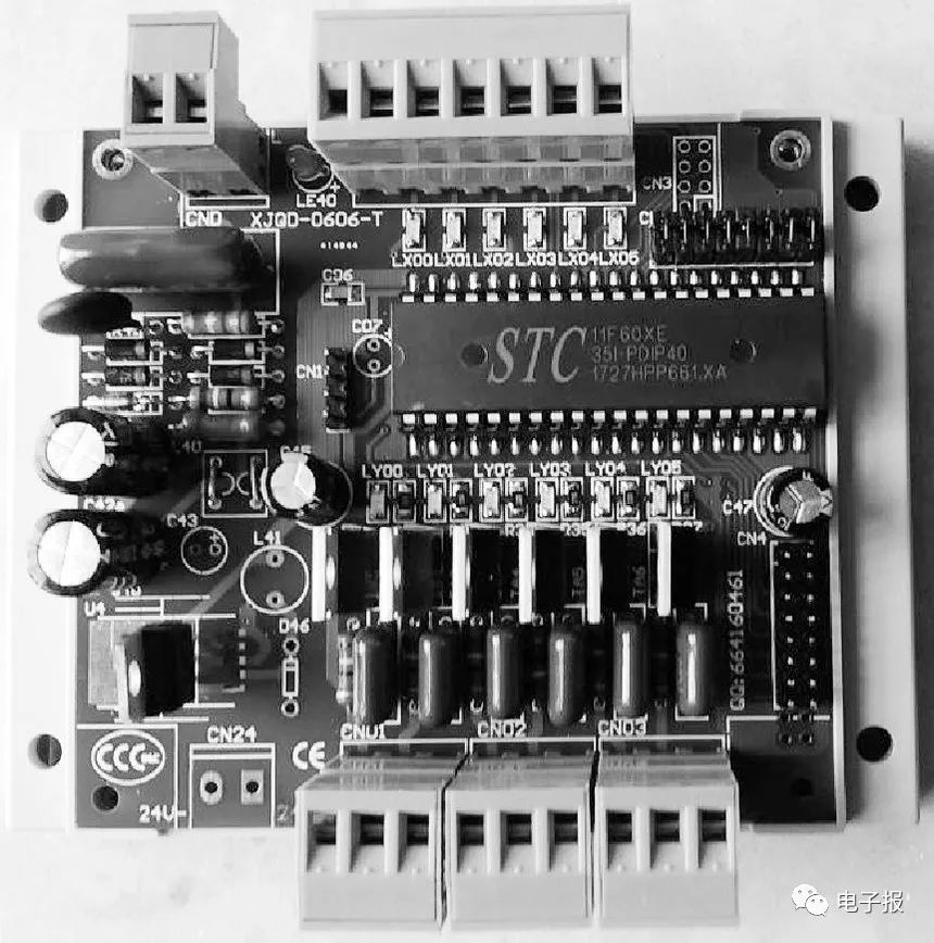 Figure 1 Controller2. Application Circuit Description The main circuit for the star-delta soft start of a three-phase asynchronous motor is shown in Figure 4. In the figure, QF1 is the air switch, KMF is the motor forward power contactor, KMR is the motor reverse power contactor, KMY is the contactor for the motor winding Y connection, and KMD is the contactor for the motor winding Δ connection. The control principle of the asynchronous motor star-delta soft start controller is shown in Figure 5. The controller’s input terminals are connected to: FR for the normally closed contact of the motor thermal protection relay, M/A for the jog/continuous operation mode selection switch, button SBT for the stop button, button SBZ for the motor forward start button, and button SBF for the motor reverse start button. The controller’s output terminals are connected to: KMF for the forward power contactor coil, KMR for the reverse power contactor coil, KMY for the motor Y connection contactor coil, KMD for the motor Δ connection contactor coil, with the contactor coil power all being 220VAC, and HL for the indicator light. This circuit can achieve motor forward and reverse rotation, jog, or continuous operation. When only forward rotation is needed, the button at terminal X4 can be omitted. If jog operation is not needed, terminal X1 must be connected to the common terminal with a wire.
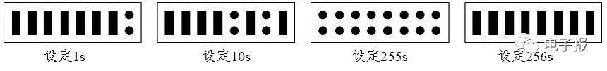 Figure 2 Controller Input and Output Terminals
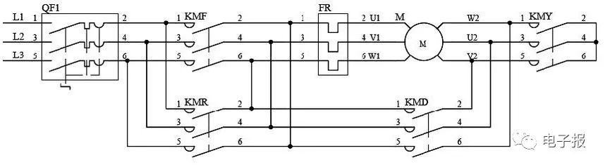 Figure 3 Start Time Setting Due to different loads connected to the motor, the start time also varies. This controller uses 1 second as the basic unit to set the start time through the binary port “CN2”, with a default setting time value of 8s. The wiring diagram for using the asynchronous motor star-delta soft start is shown in Figure 6, where the contactors, thermal relays, and other electrical devices should be determined based on the capacity of the motor being controlled.
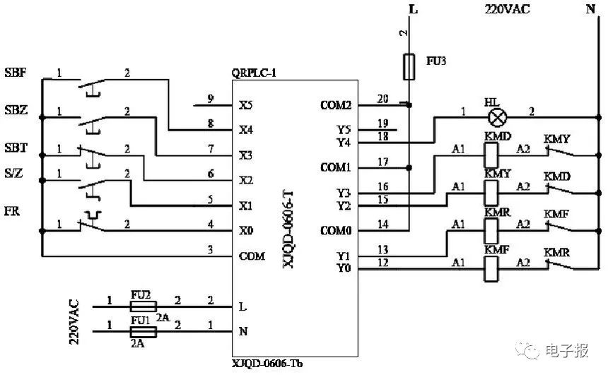 Figure 4 Main Circuit
Figure 5 Control Principle Diagram

Figure 6 Wiring Diagram◇Jiangsu Chen Jie